More Pictures and Illustrations to come soon
Introduction
This is a brief guide on soldering! What I’ll cover will not span beyond safety, equipment, and techniques pertaining to soldering via iron or air station, as more exotic tools such as digital microscopes, reflow ovens, and the like are too expensive and unnecessary for what the vast majority of people will require. Here is a list of all of the items required to perform the techniques detailed in this guide:
- Ventilation/Air Filtering
- A Soldering Iron (the Hakko FX-888D is more than sufficient for hobbyists)
- Solder
- Solder Wick
- Soldering Flux
- Tweezers
- Brass Wool
- Multimeter (Anything capable of continuity testing will suffice.)
- Hot Air Station (optional if none of the components you use/repair are BGA or have pads that an iron cannot access)
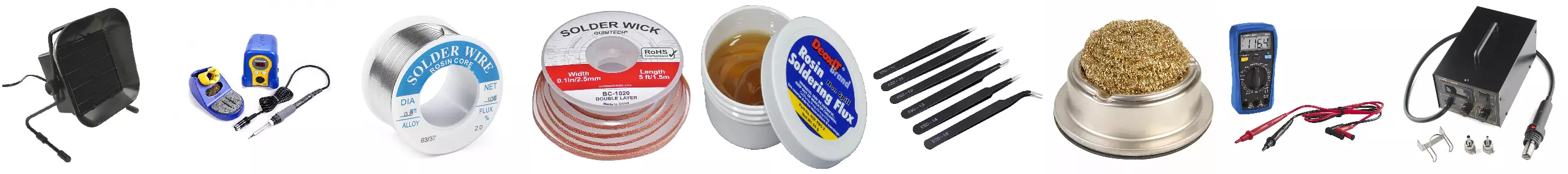 Items are in order with leftmost being an example of an air filtering system
Tips
It is highly important that you have a clean work environment free of dust and a ventilation system that either filters solder fumes or otherwise removes them. A simple fan in a closed room will do little more than recirculate fumes and allow for them to combine with other particles to create hazardous dust. Solder fumes tend to irritate the skin, eyes, and respiratory system when encountered directly, but the lead dust created in an uncleanly and poorly ventilated work space is dangerous. A mask is not a substitute for ventilation: please don’t overlook it.
If you intend on working with microelectronics I recommend getting a decent soldering station with interchangeable tips such as the one linked in the list above. A 20 dollar pipe soldering tool from the hardware store will not provide adequate flexibility in regards to either temperature control or tip size. Ensure that the smallest tip you have can make contact with the smallest leg/solder point on your project without making contact with any adjacent legs/solder points (there obviously reaches a point at which the legs of an IC will be so small that this won’t be possible.). Large tips will provide a greater surface area over which heat can be transferred, thus reducing the time required to sufficiently heat the solder joint in question and flow your solder.
Please do yourself a favor and avoid using lead-free solder unless you have a good reason to do so. Leaded solder is not any more dangerous than lead-free solder in a well ventilated and clean environment, and can help you to avoid wasting time and damaging components. The added time required to heat components, increased susceptibility to oxidization, and inferior flow consistency of lead-free solder will ensure that you waste more time, overheat more components, and use more flux than you would have otherwise. Get rosin core, leaded solder.
Soldering Wick will allow you to remove solder from your project or perform more advanced techniques on surface mount devices. Make sure you have a roll available to you at all times.
Oxidization naturally occurs on the extremities of solder and creates a barrier which can make your solder job more difficult in the best of cases, or impossible in the worst. Flux removes this oxidization and allows for your solder to flow more easily, making component overheating easier to avoid. I would grab a container of flux paste for tinning your iron and a bottle of flux liquid for other purposes.
Grab a set of tweezers to handle your electronics with. A small set should offer you enough variety to accommodate a plethora of component sizes.
Any multimeter will suffice for the purpose of checking that your solder work is bereft of unwanted shorts, but it may be smart to invest in something with more accuracy if you intend on doing more sophisticated or sensitive work in the future.
Most soldering stations come with brass wool and a holder to contain it. If your station is an exception to this axiom, make sure to order some wool and a means of stabilizing and isolating it as you run your iron through it. Your iron tip can oxidize just as the components you wish to solder; make sure you have clean brass wool on hand to address this concern when it arises.
Hot Air Stations allow for heat to be applied to multiple places at once, as well as to those which are inaccessible to traditional irons. If you find yourself routinely working with surface mount components with underside pads, ball grid arrays, or components that are difficult to remove otherwise, you should get a hot air station.
Technique
Proper Soldering
Before you proceed it’s important that you develop a proper understanding of what a desirable outcome looks like. A successful solder job really amounts to whether the joint in question is “warm” meaning that the solder and every component/board/wire involved conforms together, or “cold,” meaning that the joint and its surrounding elements were not of equal temperature. The quantity of solder required is purely dependent upon the surface area of the components/wire/board involved in the solder joint. Obviously it isn’t possible to selectively coat only the surface area of a solder joint, so the modus operandi is to simply add solder to the joint until all surfaces are covered. The image below illustrates these concepts: 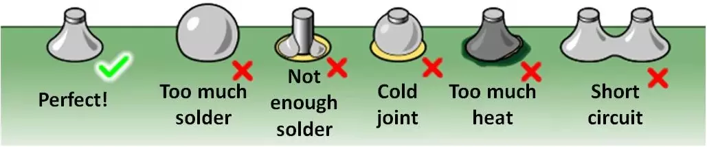
Soldering Wire
I suggest crimping wires together in most situations as the result will be less brittle and more resilient, but sometimes soldering is necessary. The most important characteristic of the wire you’re working with will be its strandedness. This alludes to whether the wire is a single, solid element, or is comprised of multiple parallel strands. If you’re dealing with solid core wire, expose your desired length of wire on either side using a stripper. Next, tin the exposed area of both wires: secure the wire, hold your iron to the exposed portion of the wire, and coat the extremity with solder. Once you have completed this process for each wire, secure one of the pieces using a vice or other stable grip. Then, while holding the other wire in one hand and the soldering iron in the other, bring the tinned sections of the wires together while applying your iron to the secured wire. Once the solder on both wires has flowed, remove the iron and use your other hand to ensure that contact is made with the greatest amount of surface area possible as the solder quickly hardens. The process for soldering stranded wires together is largely the same. Firstly, expose the wire using strippers and push the ends together such that the strands become as evenly interspersed as possible. Next, twist the connection such that both its diameter and the space between strands are minimized. Finally, heat the connection with your iron and apply solder such that the exposed area resembles a solid core wire. Apply flux to the strands if your solder doesn’t flow easily. The job is done from a soldering perspective, but I’d be remiss if I were to avoid suggesting covering the exposed section with heat-shrink or electrical tape at the very least.
Through Hole Components
The vast majority of the users of this guide will find themselves dealing with through-hole components. Thus, I’ll try to avoid sparing any details. Firstly, position the component you wish to solder relative to the holes which will receive it and any indicators of how it should be oriented. Examples of such indicators are dots, lines, or indentions on the component, and similar such markings on the PCB’s silkscreen (The silkscreen is the colored, usually white, descriptive component of the circuit board just beneath the solder mask.). How these markings correspond to the pinout of the component in question can be ascertained from the datasheet or drawing document. Here is an example of a component datasheet from Texas Instruments. On page 5 the pinout of the component can be found along with a small dot on the top left of the package indicating how it should be oriented. Part numbers can be found printed on the component itself or from a component list associated with the PCB you’re working with. Part orientation can be established through bench testing in the absence of these options, but you should never install a component without absolute assurance that you’re doing so correctly. Certain components such as resistors are not sensitive to direction. Next, determine how you want the device you’re soldering to be positioned once installed. Most often this means pulling as much of the legs through each hole as possible, but there are certain instances in which it makes sense to make use of the flexibility that through hole devices offer. For example, switch mode power supplies sometimes include vertically mounted resistors or other such components to make room for their large capacitors and transformers. You’ll finally be ready to begin soldering once you’ve adjusted the legs and know exactly how it is you expect your component to look when you’ve finished.
Prepare the iron and push the component’s legs into the board. Next, secure the component. In many cases you can simply turn the PCB over and use its weight to secure the device, but this will not work in instances where precise positioning is desired. In these cases, a board vice and grippers are helpful. A less graceful, but commensurately simple solution is to temporarily tape the device to the board. Make sure to avoid getting tape on the legs of the component, as it will melt and make for a wonderful smell and mess. Carefully and gently bring your soldering iron to the outermost pin of the component on the underside of the board. Solder this pin and the outermost pin opposite of it. Now your device should be nicely secured such that you can confidently solder the rest of the pins. Be careful to apply the iron to the pins only for as long as necessary to make a clean joint, otherwise the device could incur damage.
It’s good practice to check your device for continuity (or lack thereof) once you’ve finished soldering. Simply probe each pin and those adjacent to it to ensure that they’re isolated as they should be. Reference the datasheet and pinout for assurance of the function of each pin, as multiple pins could be connected together within the device itself. A beep from your multimeter indicates a short, or direct connection, while the absence of noise demonstrates the opposite. This is seldom the case for through hole components, but it sometimes occurs that the legs of a component are so close together that the probes of your meter touch when measuring. In this case, having access to the PCB layout is crucial, as it will allow you to easily determine which trace(s) are connected to the pin you’re attempting to probe. Touch one probe to a via or pad which is connected to the pin you’d like to check, and touch the other probe to this same pin to check to see that it’s correctly soldered, or to those pins surrounding it to ensure that it’s isolated.
Removing through hole components can be a little tricky, especially for those which have numerous pins. I’ll detail a few methods ranging from those which require all of the tools mentioned in the list in the first section of this guide, to those which require the bare minimum. If you have access to a hot air station and all of the pins on the device you wish to remove are close enough together such that the solder on each pin can flow concomitantly, simply secure your board using a vice or another such tool and apply heat to the pins on the back of the board until the solder starts to flow. Firmly grasp the component with your tweezers and pull the component and its legs through the board. Lastly, clean up any residual solder from the holes on the board using your iron and wick. Simply place the wick over the solder you wish to remove and apply your iron until the wick begins to absorb it. It helps to use tweezers to avoid burning yourself. Desoldering becomes a lot more cumbersome with access only to an iron, but it is of course possible with patience. The most tedious aspect of this process will be ensuring that not only have you removed all of the solder from either side of each pad, but also from within each hole. The difficulty in this is exacerbated by the rigidity afforded to each leg by its neighbors, meaning that determining which legs are loose isn’t trivial. Start by applying a small amount of flux to any leg of your choosing, and start to apply your iron and wick. If you’re lucky, you’ll have access to the top and bottom of each leg. Regardless, keep applying flux and attempting to remove the solder from within and around each pad/hole. The more astute readers of this guide will question why it is that I’d suggest using flux when wick already contains it or rosin in most cases, but the tedium of this process will assuage such skepticism. If you can’t seem to remove all of the solder in a particular hole, reapply solder to the leg and attempt to remove it again. Start lightly wiggling the component once you’ve freed a few of its legs to get a feel for what remains to be removed. If you’ve determined that the component you’re working on cannot be removed in this fashion, or you’ve given up, you may have to resort to cutting troublesome legs and cutting your losses. This will of course prevent the reuse of the component, or in the best of cases make it difficult to resolder. However, if you’re removing a component it is likely not functional or in need of replacement. In any case, this will be for you to decide.
Surface Mount Components
Most PCBs made within the last few decades will consist almost entirely of surface mount devices. The primary distinction between through hole and surface mount is of course that surface mount devices have legs which rest on pads rather than through the board in question. This allows for increased circuit complexity not only within the device itself, but within the PCB as well. This is a consequence of the fact that the holes required to accommodate through hole components impinge upon each layer of the PCB, thus obstructing board space that could have otherwise been used for traces, vias, or other features. Make sure to avoid packages/components that have underside pads or ball grid arrays if your lab lacks a hot air station. In any case, check the datasheet or drawing of the component you’re working with to determine how it should be oriented on the PCB, just as in the previous section. Next, determine a point to presolder to hold your device in place. This task is especially simple in cases where the chip in question has an underside pad. If so, apply a thin layer of solder to the pad, or pads, on the board side using your iron. Be sure to remove any excess solder using wick, as it could flow to adjacent pins and create a short when you later attempt to position the component. Choose an easily accessible outer pin to presolder otherwise, applying the same principles as above. Now, flow the solder using either your iron or hot air station, depending on what your chip demands, while holding the component with tweezers in its correct orientation with respect to the board. Ensure that every foot/pin of your component aligns with the pads on the board and set it down. Keep applying heat, whether it be from your air station or iron, to the device until the presoldered board pad forms a solid connection with its respective component leg/pad. Remove the heat and inspect the device. If the component is level, secure, and properly aligned, you’re ready to proceed. Otherwise, reapply heat and make adjustments until this is so. Don’t be afraid to use magnification on devices with small legs. I like to start this process by preemptively soldering a few legs to the board for the purpose of making sure that additional heat doesn’t dislodge the component. Next, ensure that your soldering iron is equipped with a tip no larger than the legs of the device you’re attempting to solder. I’ll cover what to do in cases where this isn’t possible or in those in which great dexterity is necessary to solder individual legs shortly. Simply apply your iron to each leg and create a nice joint at each one. There is no need to be overly conservative: if you apply too much solder such that two or more legs become conjoined, simply remove it with wick. Doing this intentionally is actually an effective method to solder entire rows of small legs. Slowly and gently apply your iron to the corner leg of a row and apply solder until it flows. Softly drag your iron along the row of legs while following it with solder. When finished you should have a uniform blob of solder spanning the entire length of the chip. Now, repeat this motion with your iron with a strip of wick placed over the solder. Wick the excess solder off until all that remains is that which is keeping the legs in contact with your board. It is of course possible to presolder all of the pads for a component and flow them with a hot air station, but this creates less reliable joints than the aforementioned methods. A more effective variation of this method is similar to how machines solder boards, but it requires soldering paste: If you have a hot air station and soldering paste, apply a conservative amount of paste to each pad on the board. Then, simply apply heat with a hot air station until the solder flows while gently holding the chip in place with tweezers. As always, wick away excess solder to avoid shorts. Check your work for continuity once complete as explained in the third paragraph of the previous section.
Surface mount components are either trivial to remove or almost as irritating as through hole devices. Having access to a hot air station is typically the primary factor in determining whether or not this is the case. If you intend on using a hot air station, inspect the board you’re working on to determine if neighboring components need to be shielded, otherwise their solder joints may be disturbed. To accomplish this, simply tape aluminum strips over the section of the board in question. Provided you’re quick enough, a piece of cardboard may even be sufficient. However, it may not even be necessary to cover adjacent components if the one you wish to remove is small enough to be completely saturated with heat without much maneuvering of the nozzle of your hot air station. In any case, have your tweezers on hand and begin to heat up the legs and their corresponding pads with hot air. You may want to secure the component with your tweezers once the solder starts to flow depending on how small it is such that it doesn’t take flight or disturb its neighbors. Move the heat gun around the device while evenly supplying heat until all of the solder begins to flow. Be careful not to overheat the device by maintaining heat in one area for too long or applying heat directly to the chip itself, although this will be unavoidable in instances where a chip has underside pads. Once this has been achieved, simply lift the component off the board with your tweezers and set it aside. Clean up the board with an iron and wick to prepare the pads should you intend to reuse them. If all you have at your disposal is an iron, remove as much solder as you possibly can from each leg using your wick. Slightly nudging or wiggling legs to check if they’re loose is effective just as with through hole devices, but it will be harder to notice as the legs of surface mount components are much shorter. I suggest applying wick directly to the pads of the board while pushing it into the component’s legs to remove as much solder as possible from their underside. Don’t be afraid to use flux. The fool proof way to disconnect each solder joint is tedious, but effective. Apply your iron to a pad, or multiple pads if they’re sufficiently small and you’re commensurately skillful, and use your tweezers to lift the legs of the device until they no longer make contact with their pads. Wait for the solder to harden such that the legs don’t immediately reconnect to the board, and repeat this process until the chip is free.