Introduction
This machine is colloquially refered to as the "Hybrid HDD," but it's
really an electric over hydraulic HDD. This project is a stepping stone
before contending with the massive undertaking that will be creating a fully
electric equivalent. The fully electric drill will consist of completely new components
throughout the whole of the machine, whereas this "hybrid" drill is similar to existing machines
but with batteries, an electric motor, an inverter, and a high power converter rather than
an internal combustion engine.
I've written control software pertaining to the high voltage battery, power converter,
and high voltage DC/DC converter; made modifications to machine's existing displays and user
interfaces to accommodate for the new components, and made a few boards to control brakes and
determine whether or not the high voltage bus is precharged. These contributions are detailed
in the paragraphs below.
Component Integration
Battery
My most important contribution to the project has been the development of control software for
the high voltage battery packs and their accompanying management unit. Each pack has a voltage range
of around 250 to 400 volts and a total energy of around 40 kWh. The system is configured with two of these packs
in series, both of which are connected to an interface unit filled with contactors and fuses to
protect the system and batteries from undesirable operating conditions.
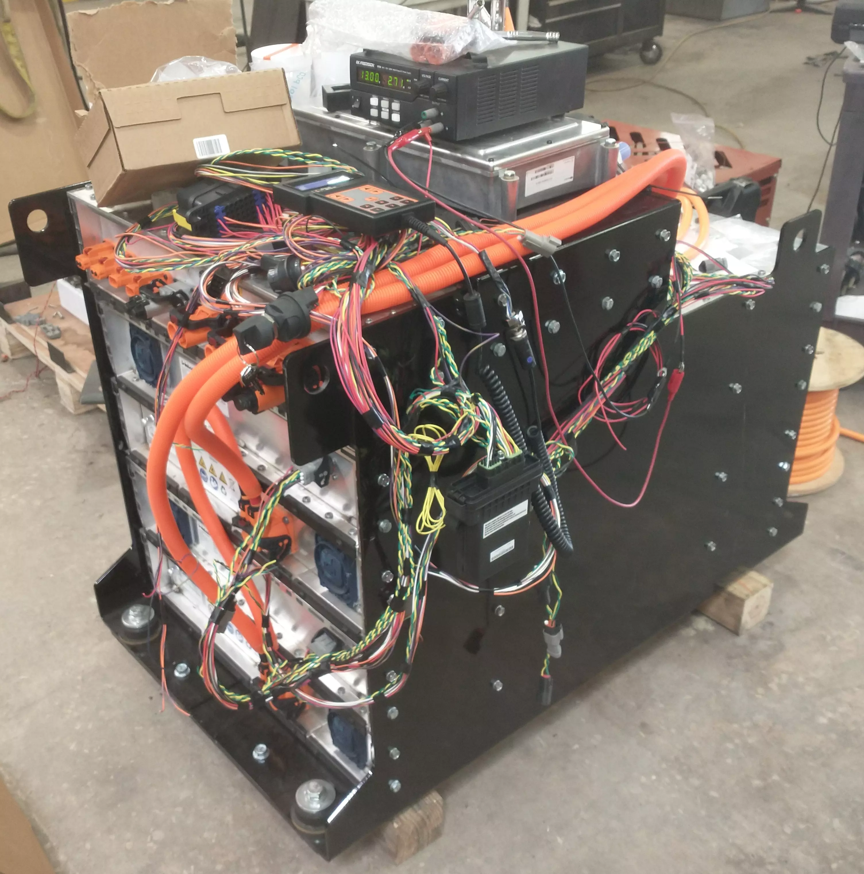
For the sake of brevity I'll
refer to this combination of battery packs and interface unit as "the battery," which can be identified
in the picture above by the purple powder-coated steel flanking it on either side. The two battery
modules are connected by the large orange plugs on the bottom left of the image, atop which
is the interface unit. Our test harness rests on top of the battery, along with a DCDC converter,
which my software also controls, that creates a 12 volt bus from the battery output. A power supply
is resting highest on the stack and acts as a substitute for a lead acid battery for testing purposes.
Finally, the controller running my software can be seen dangling to the side of the battery.
My code involves performing a number of checks on the individual components of the battery as well
as the vehicle more generally. Once these checks pass my controller begins to communicate over
CRC
protected CAN. This redundancy
check increases the safety of the machine, which is of course desirable in a system of such high voltage.
If all is well, my controller commands the battery to close its contactors, thus connecting itself to
the machine's high voltage bus. By this stage my controller will have already configured the DCDC
converter, which will begin to step the high voltage bus down for the purpose of charging the
machine's lead acid batteries and providing logic level power for other controllers and displays.
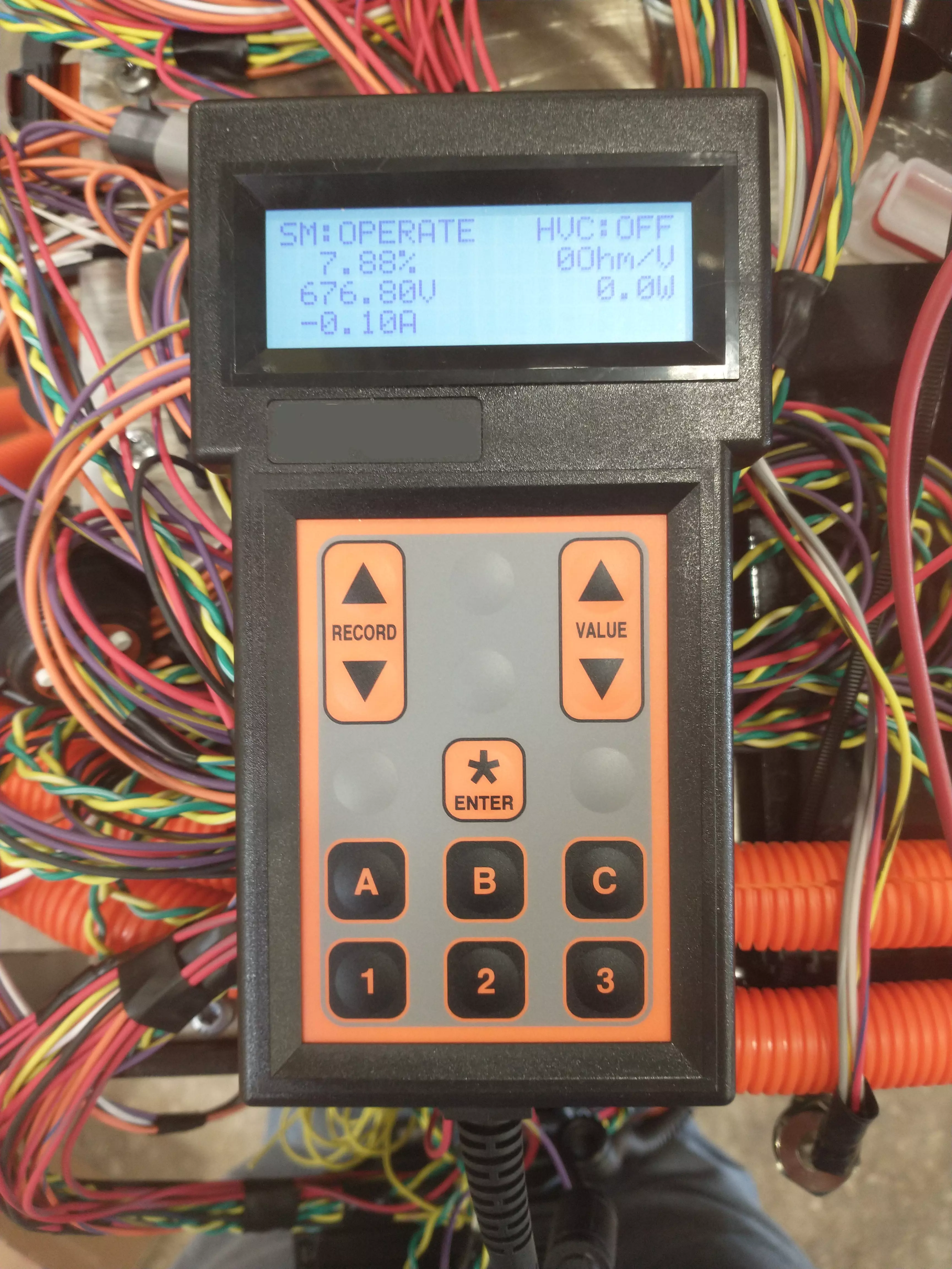
The above image is of the interface I made for my battery code on a diagnostic tool.
This tool communicates directly with the controller via a serial connection and can be programmed
to view and edit various system parameters. The screen showcased within the image contains the state
machine status, battery state of charge, voltage, current, status of the high voltage control, isolation
resistance in ohms per volt, and the output power of the battery.
Power Converter
The drill needs to source power externally due to the removal of its internal combustion engine.
This necessitates the implementation of, at the very least, a means of charging the machine's battery.
The three channel interleaved boost converter and rectifier unit pictured below addresses this problem.
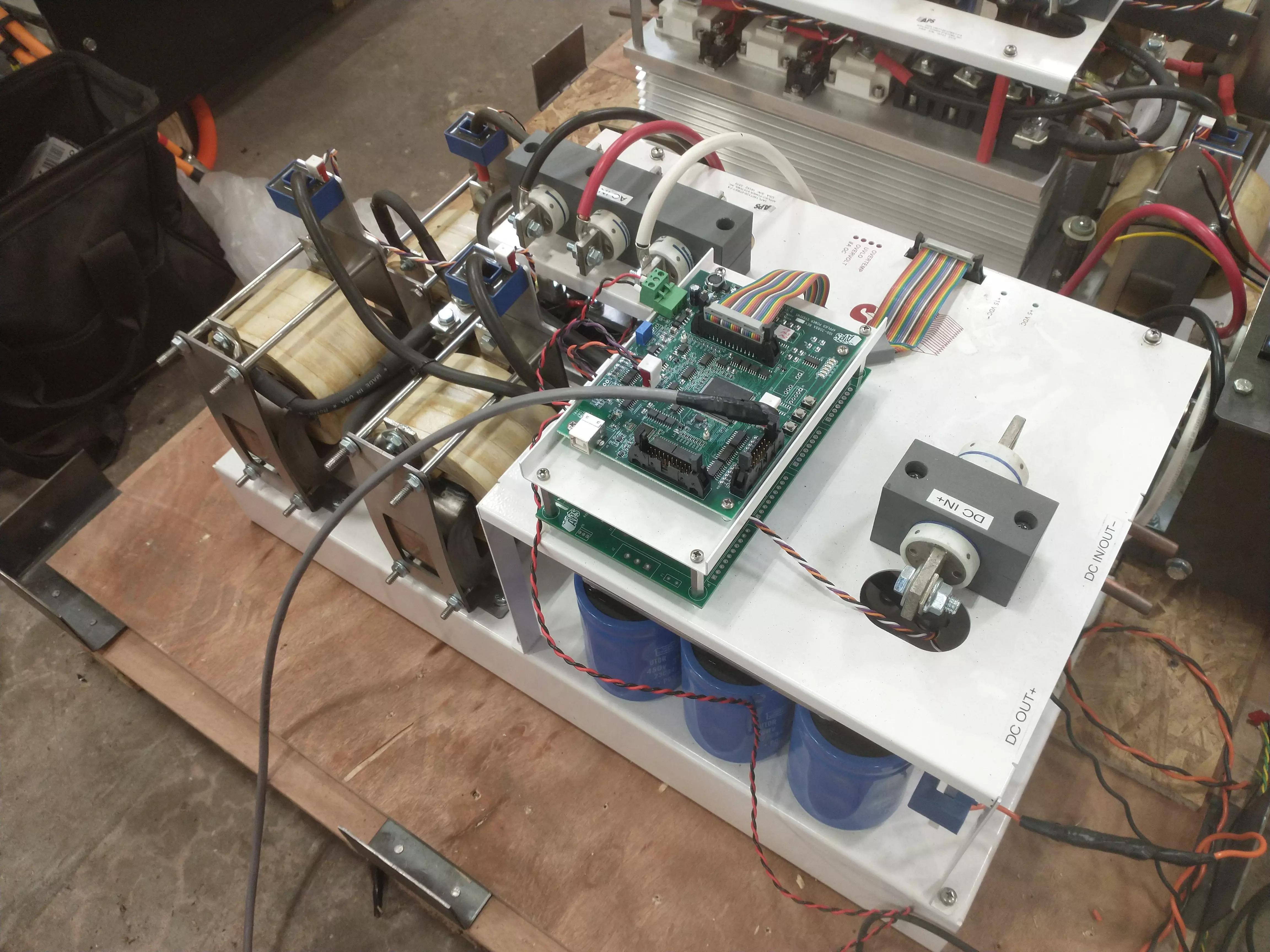
The converter sources power in the form of three phase AC, which it rectifies
into DC using a
SCR based three phase rectifier. This rectified voltage is passed into a three channel interleaved
boost converter comprised of custom wound inductors and high voltage
IGBTs where it is boosted to a voltage depending upon system load
and battery state of charge as determined by our controller.
Circuit Boards
My intitial approach to the pre-charge measurement board for this machine was to use a similar design to what I created for our electric trencher,
but I was met with two problems. Firstly, the nominal voltage of this machine is far higher (over ten times higher) than that of the trencher, making isolated voltage conversion prohibitively difficult.
Secondly, none of the isolated amplifier style integrated circuits that I used on the trencher's pre-charge circuit are in stock at any electronics distributor.
These two issues, coupled with the necessity of such circuits in electric vehicles, inspired me to create a universal design capable of being applied to vehicles of numerous voltages.
Here is the first rendition of my universal pre-charge measurement circuit:
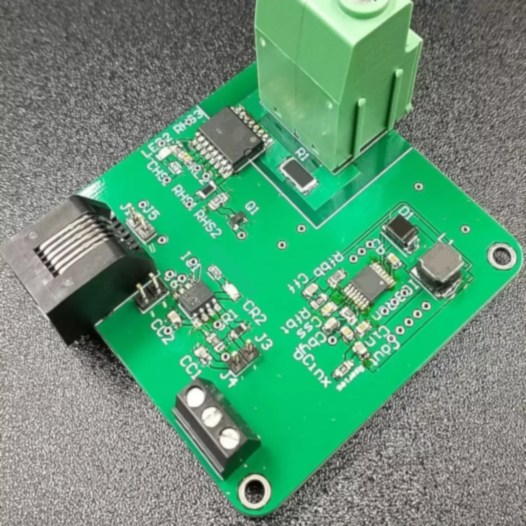
I won't detail how the board functions, but it's capable of handling voltages up to a kilovolt while costing half as much as the less versitlie trencher pre-charge circuit.
In the future I plan to change the RJ connector to a micro-usb connector such that the board can be connected to and interfaced from a dedicated computer application.
The application will allow any user to modify operating characteristics of the board and view lifetime data.
Here is one of the two simple brake driver circuits that will be used to charge the brake coils on the drill's ground drive:
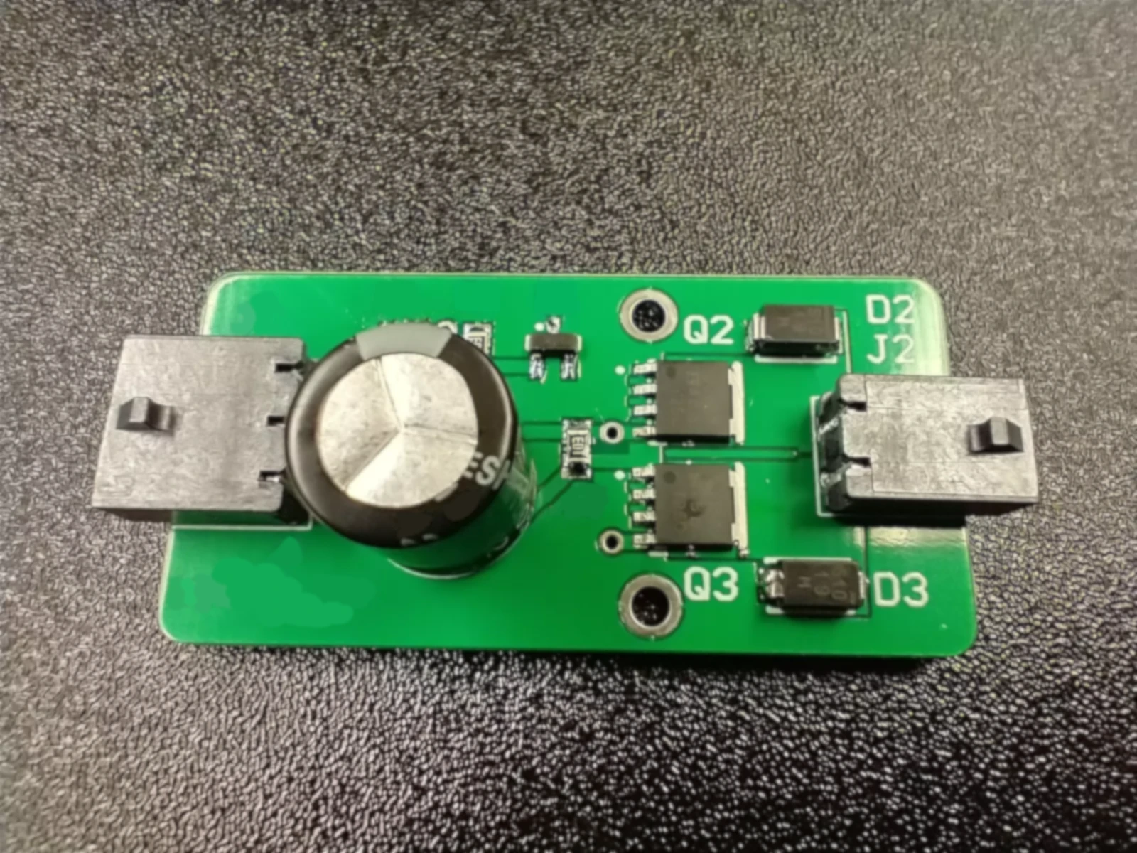
Each board is capable of driving and discharging two coils, as can be observed by the two diodes and MOSFETs on the right side. The machine's brakes will be active with a low input, and off with a high input.