Introduction
The origin of this project involved a speculative, ostentatious bid and the “CrowdStrike” server outage. This combination resulted in me obtaining a Mini Cooper for cheap, though it was not without its issues. Almost none of these issues were related to the subject of this article, the rebuild of a BMW N12 engine, but the temperamental nature of this family of engines made the rebuild justifiable, especially with its age and mileage. The intention behind the overall rebuild of the vehicle and its engine was to provide my friend with the ability to own his first car at an affordable price. As such he provided the majority of the images used in this article, and suggested that I write it.
Initial Rebuild
Disassembled Engine
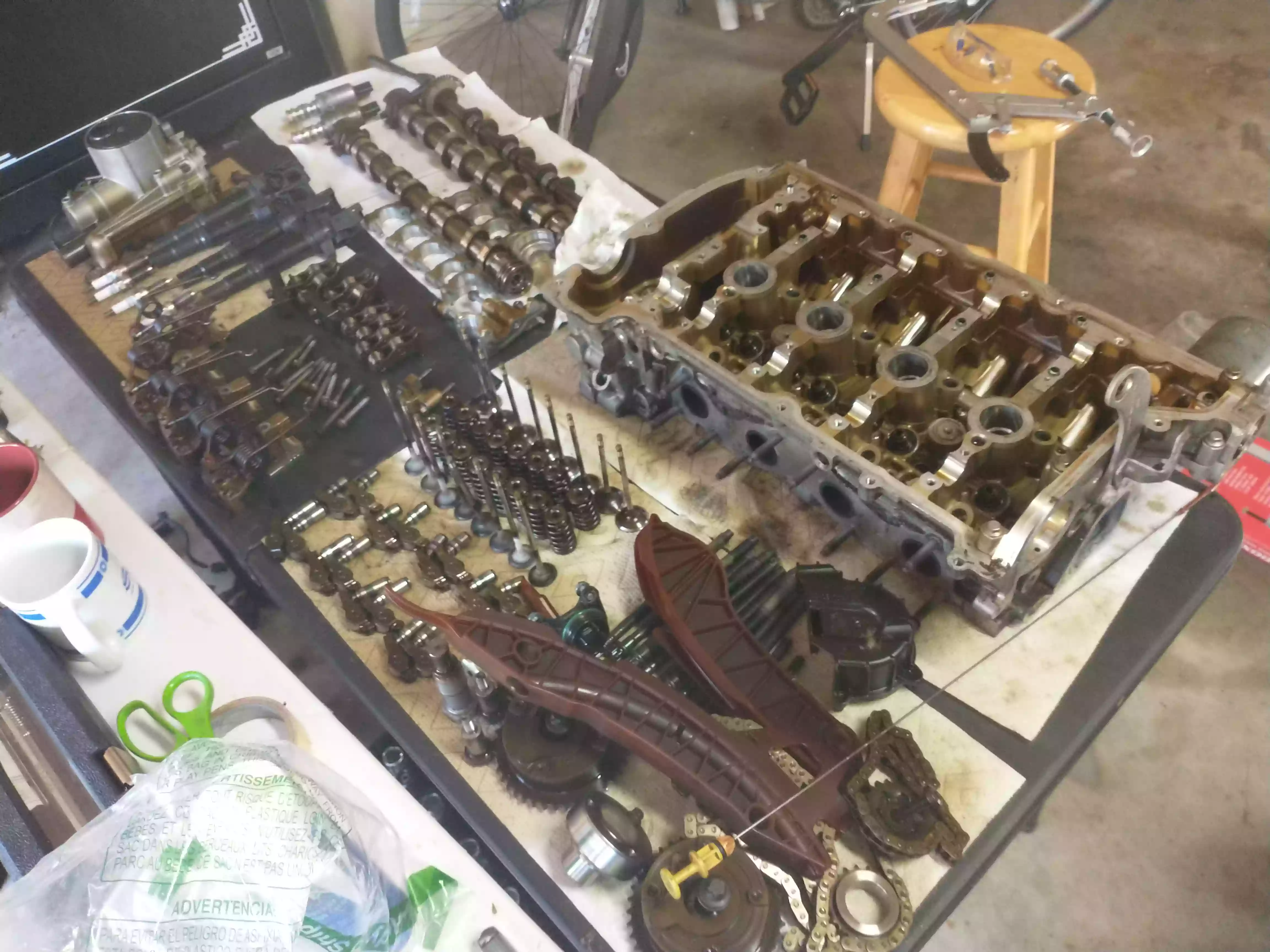
Of note in the first image are the three lobed shafts next to what BMW refers to as their “VANOS Solenoids” at the top right of the image. The N12 is a dual-overhead CAM design, but uses BWM’s “Valvetronic” system, hence the third, “eccentric” shaft in addition to the intake and exhaust shafts. This additional shaft uses springs, an electronically controlled worm-drive motor, and intermediate arms to vary the degree to which the intake valves are opened during the engine’s intake stroke.
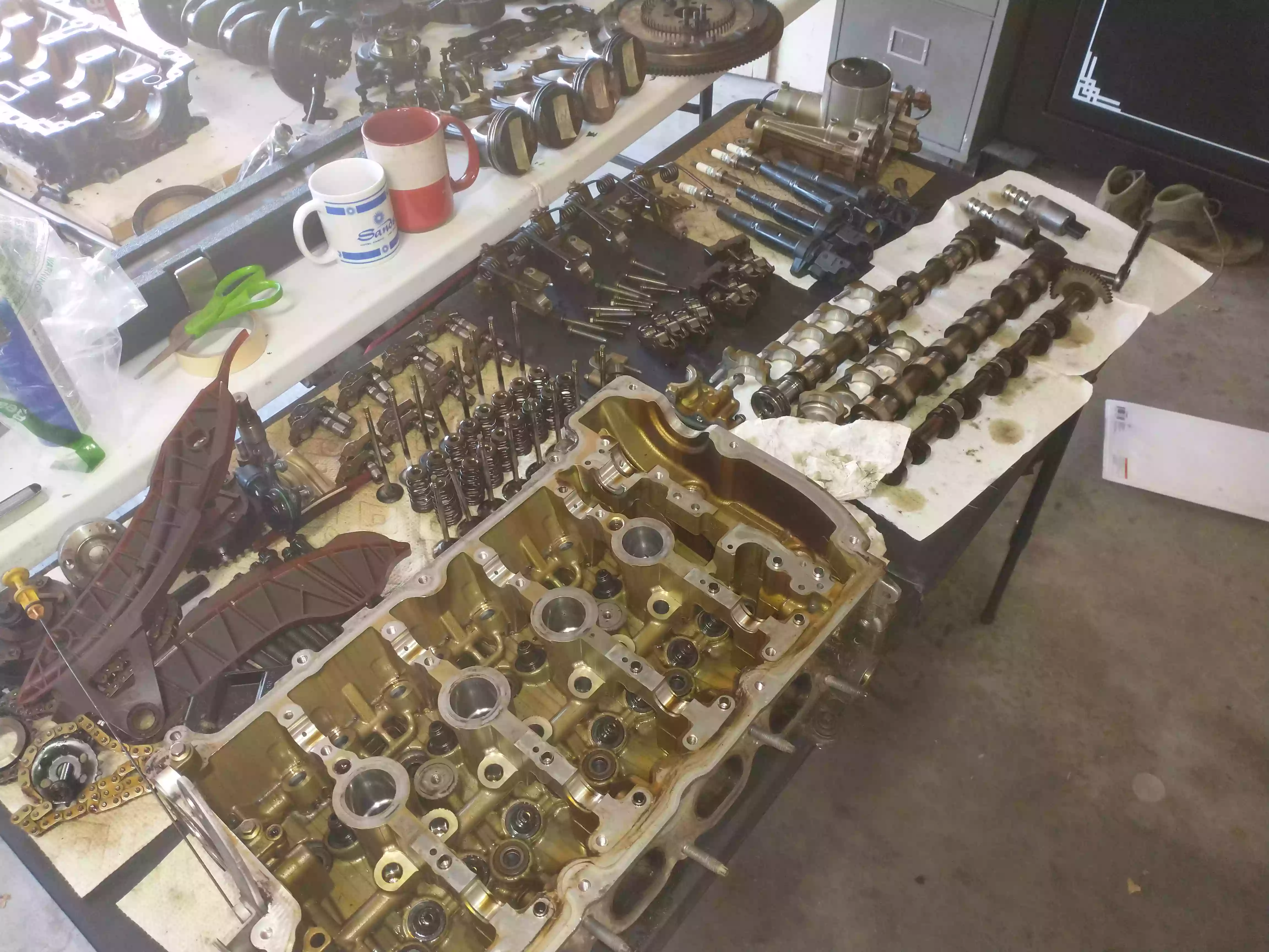
In addition to the intake variability provided by the Valvetronic system, is the variable valve timing enabled by BMW’s “VANOS” system. The N12 engine is equipped with a “Double VANOS” system, meaning that it can advance or retard both intake and exhaust camshaft timing. The two VANOS gears that attach the timing system to the camshafts can be seen at the bottom of the below image underneath the dipstick and timing guide. Above and to the left of the timing components are the traditional valvetrain elements, comprised of the valves, springs, “keepers,” and hydraulic rollers. Further up and to the left are the Valvetronic components: the intermediate arm and its springs, as well as the intermediate rollers. On the right of the image is of course the head of the engine.
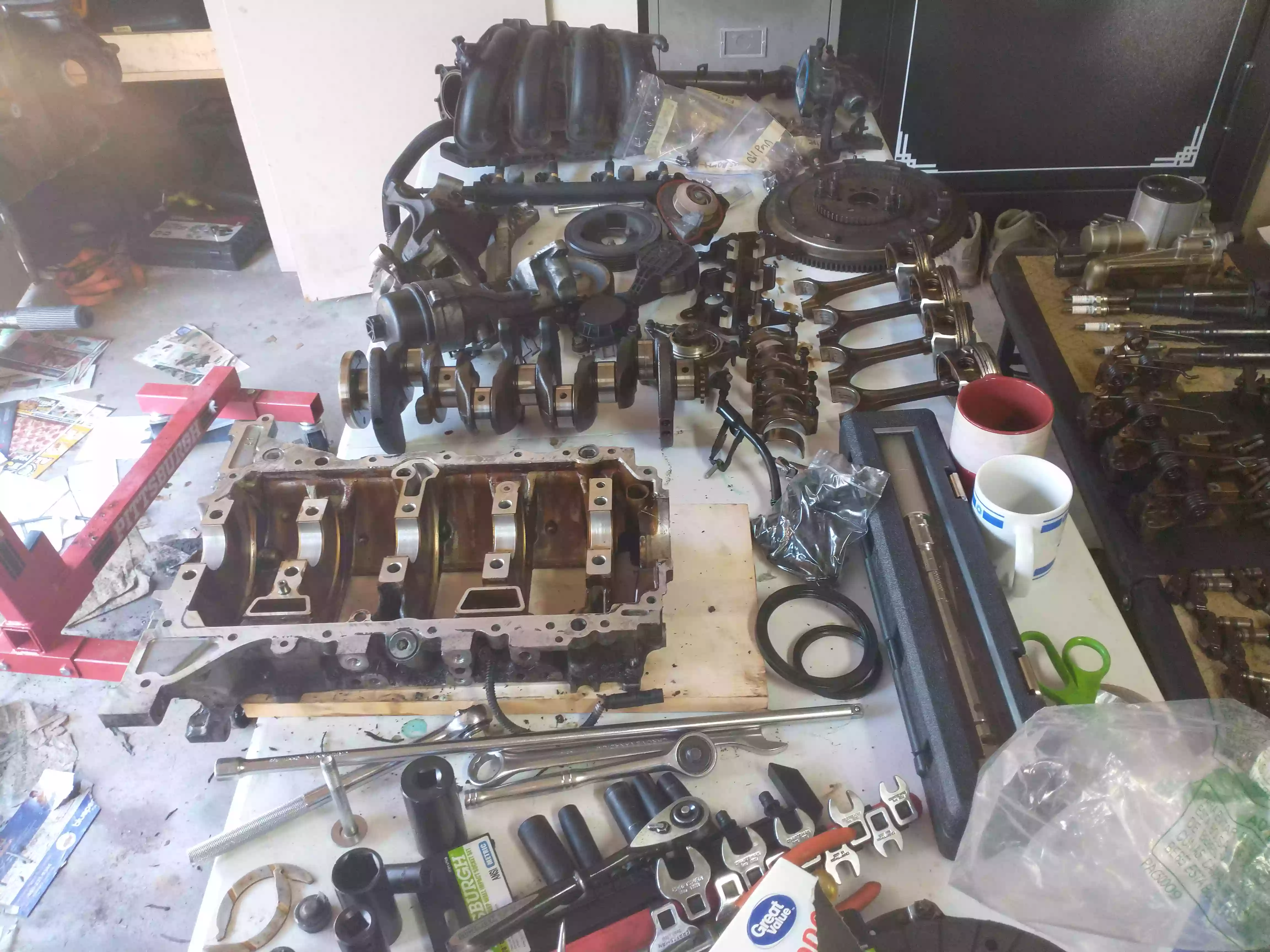
The below image showcases all of the crankcase related elements of the engine including the rotating assembly, the crankcase itself, pistons, and connecting rods in addition to the intake manifold, fuel rail, flywheel, oil filter housing, and main seals. The wear on the main, rod, and thrust bearings was minimal considering the mileage of this engine. The main and thrust bearings still measured in accordance with factory specifications, thus I only replaced the rod bearings.
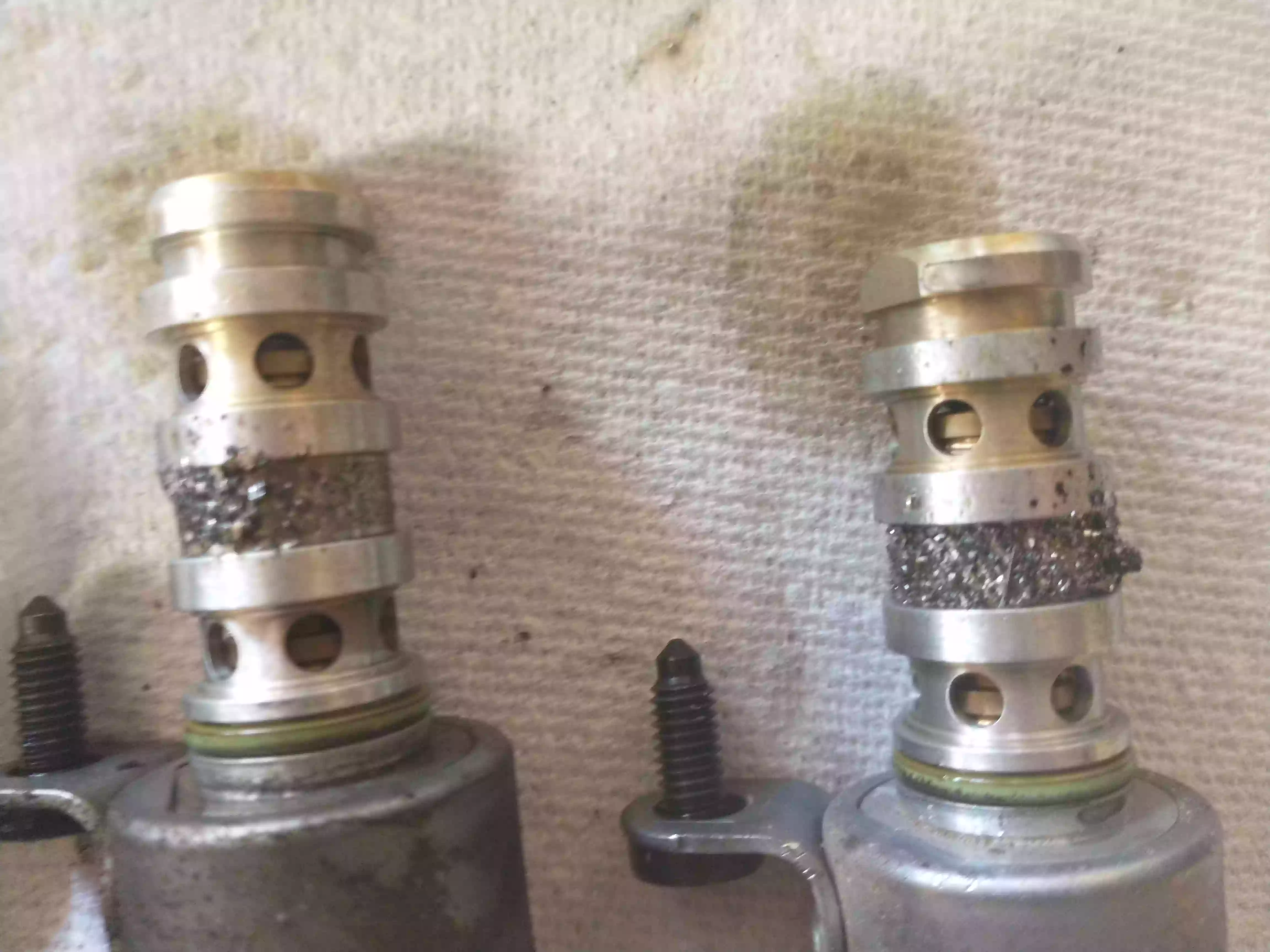
Valvetronic equipped engines are notorious for having their solenoids collect bearing material and other particulates under excessive oil change intervals. This engine was certainly no exception to this rule, as can be seen in the below image, as both intake and exhaust solenoids were almost completely clogged. However, even after having completely disassembling the engine, I still can’t say for certain where all of this material came from. The configuration of the oiling circuit of this engine suggests to me that the wear must have occurred somewhere within the head, but none of the shafts or their journals appear to have sustained notable wear, nor did the crankshaft or its bearings. In any case, I replaced both solenoids as their functionality was heavily restricted by the presence of metal shavings on their filters.
Reassembly
Below is the first picture of the reassembly process. I installed new pistons rather than only replacing the rings of the original pistons as the price difference between the two options was negligible. The second compression ring of each piston was far too large, thus I had to file them down such that their gaps were within tolerance. I erred on the side of looseness when doing so to be safe.
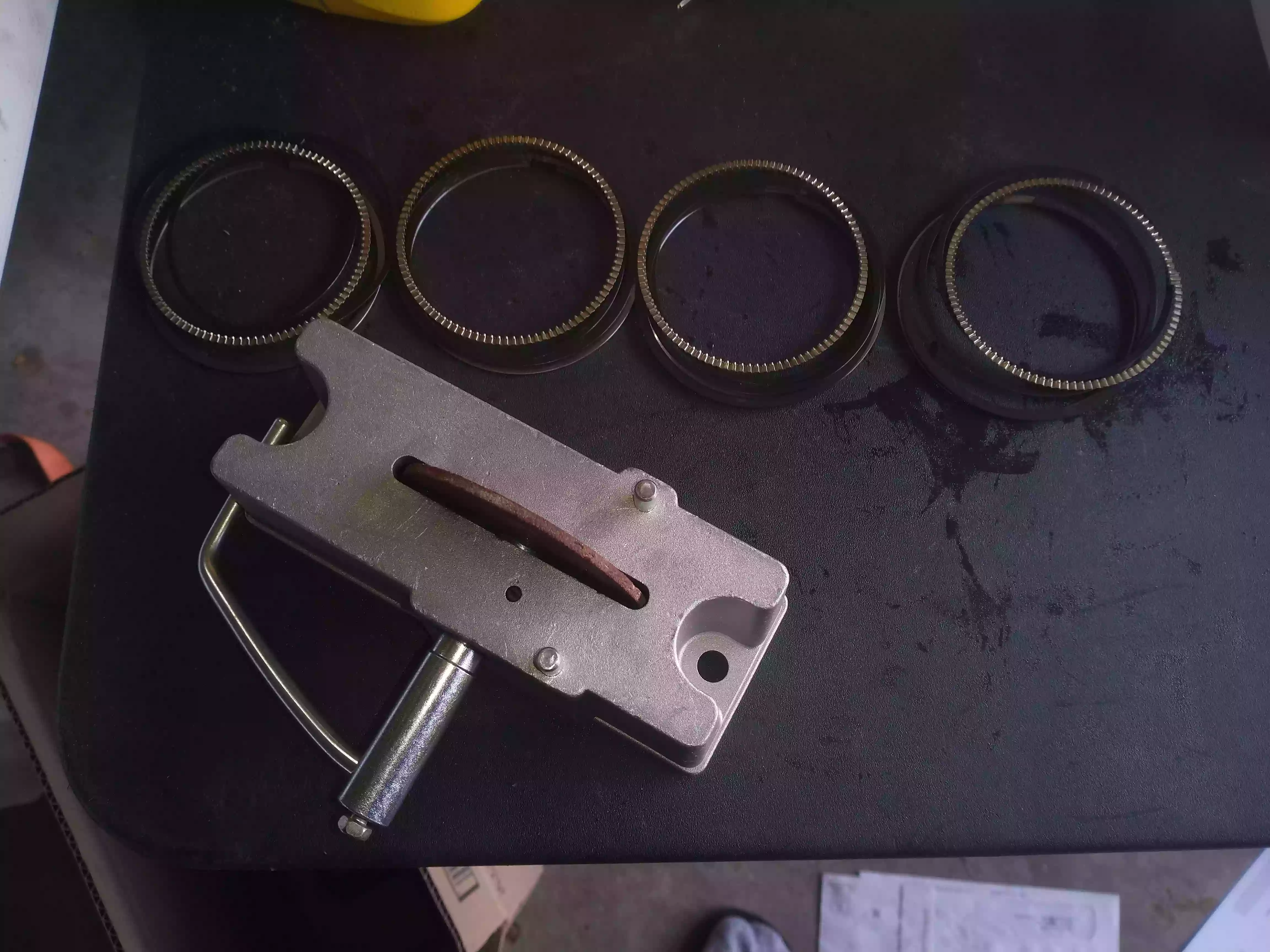
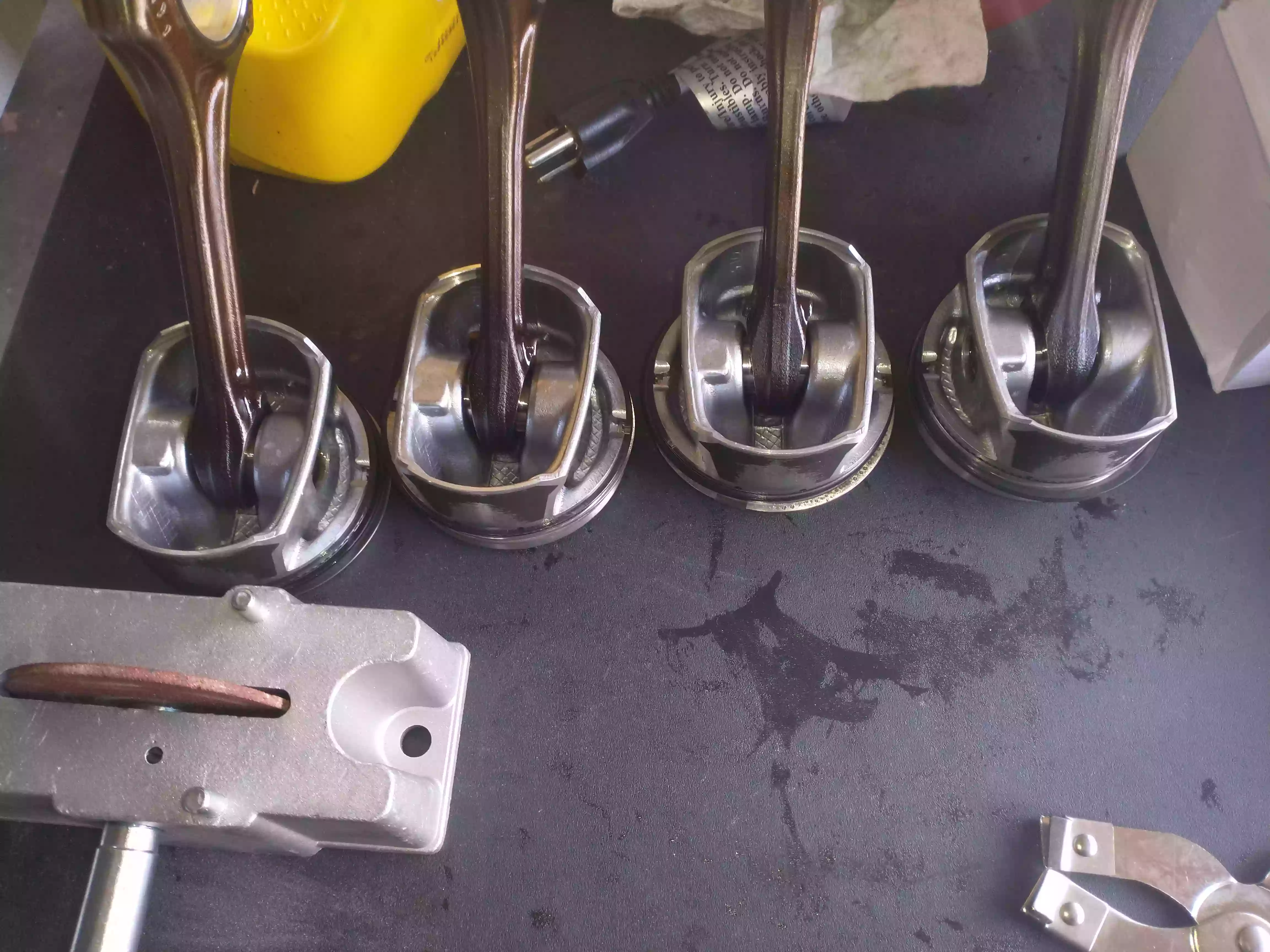
Here is a picture of the filed rings installed on their respective pistons, attached to their connecting rods by virtue of their new wrist pins.
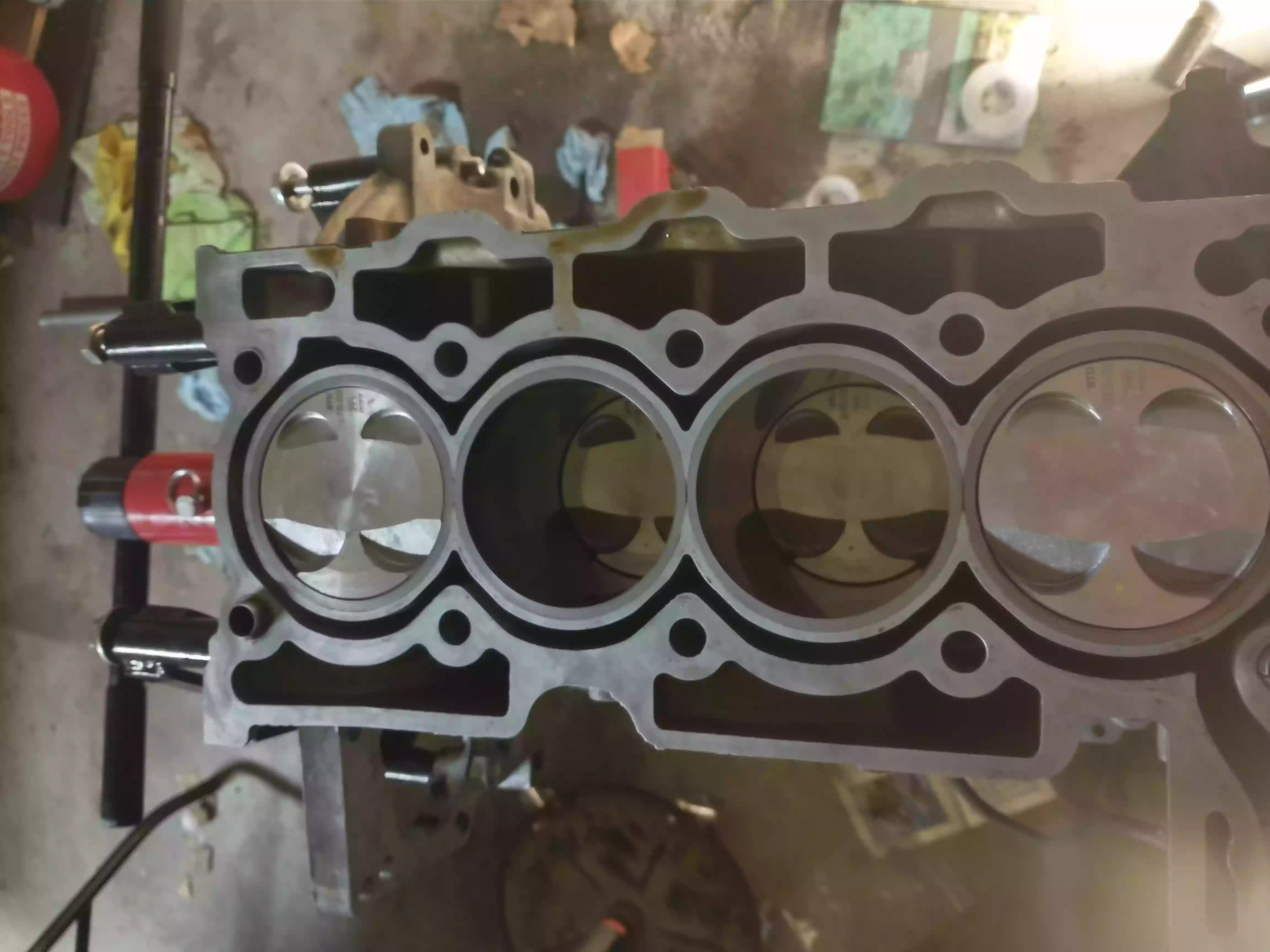
I replaced connecting rod bearings, as I mentioned earlier, but the thrust and main bearings were within tolerances to be considered new, thus I reused them. As you can see, I cleaned and measured the mating surface of the block and determined it to be acceptably flat to not need resurfacing. It took me 3 hours to install the pistons and rings as the tool I used to do so was less than useful, but the job was done nevertheless.
After reconstructing the shortblock I assembled the head and valvetrain separately from the engine stand, installed a new head gasket, installed and adjusted a new timing system, and hand cranked the engine a few times to verify my work. I’m thankful that I did so before reinstalling the engine into the vehicle, as I had mistakenly installed the intake rollers on the exhaust side, and vice versa. The improper height of the rollers caused one of the exhaust stems to chip, alerting me to the error that I had made.
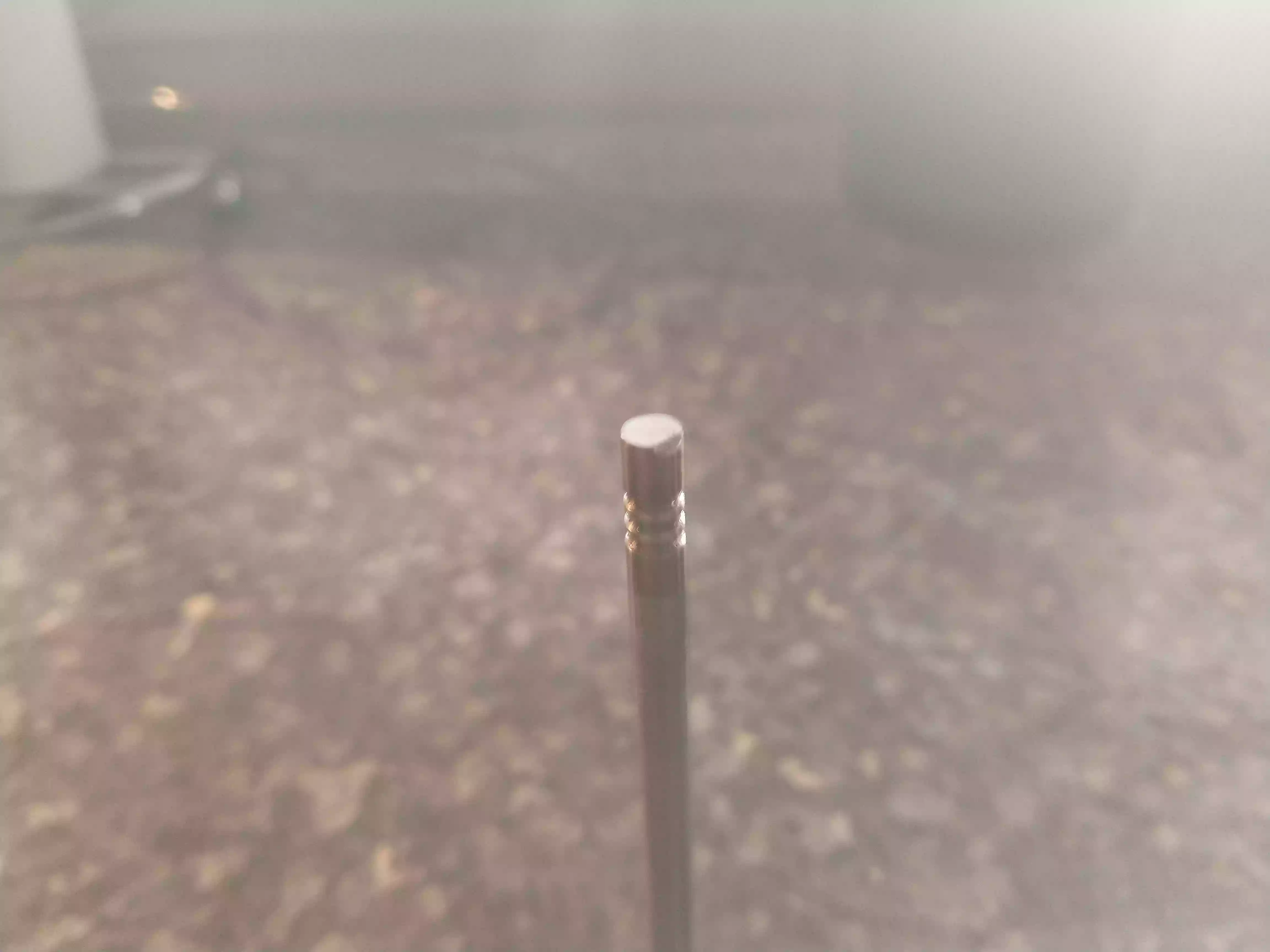
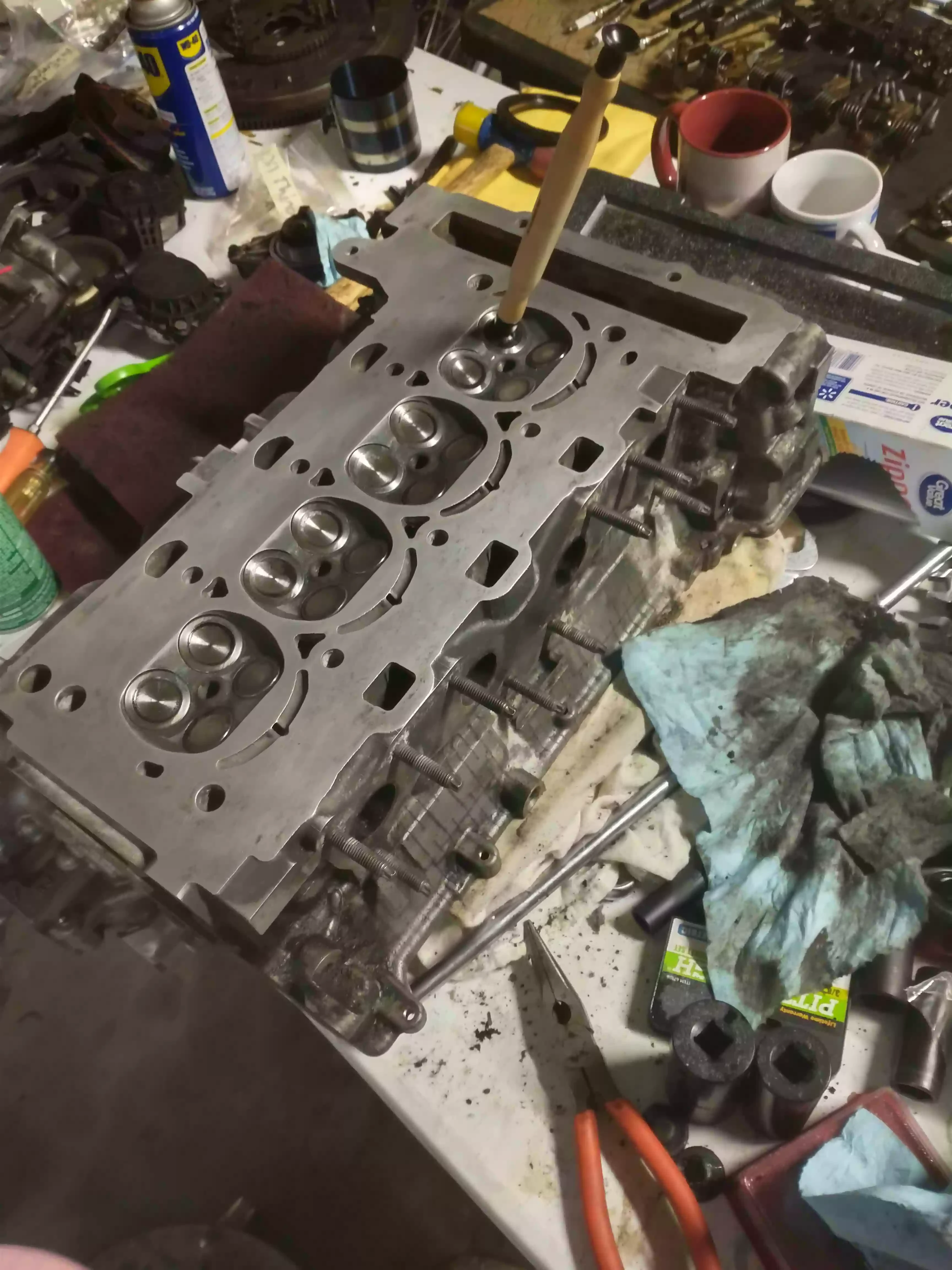
Scouring the internet for replacement valves demonstrated few affordable options, so I opted to buy an entire new set of valves and hand lap them. This process was arduous but worthwhile, as my freshly lapped valves seem to create a more convincing seal between the valves and their seats over those which were replaced. The lapping process involved lubricating each individual valve stem and guide, coating the rear of the valve in an abrasive lapping compound, using the suction tool pictured below to conform the valve seats to the shape of their accompanying valve, and finally removing any trace of the abrasive compound from the valves, stems, and the head.
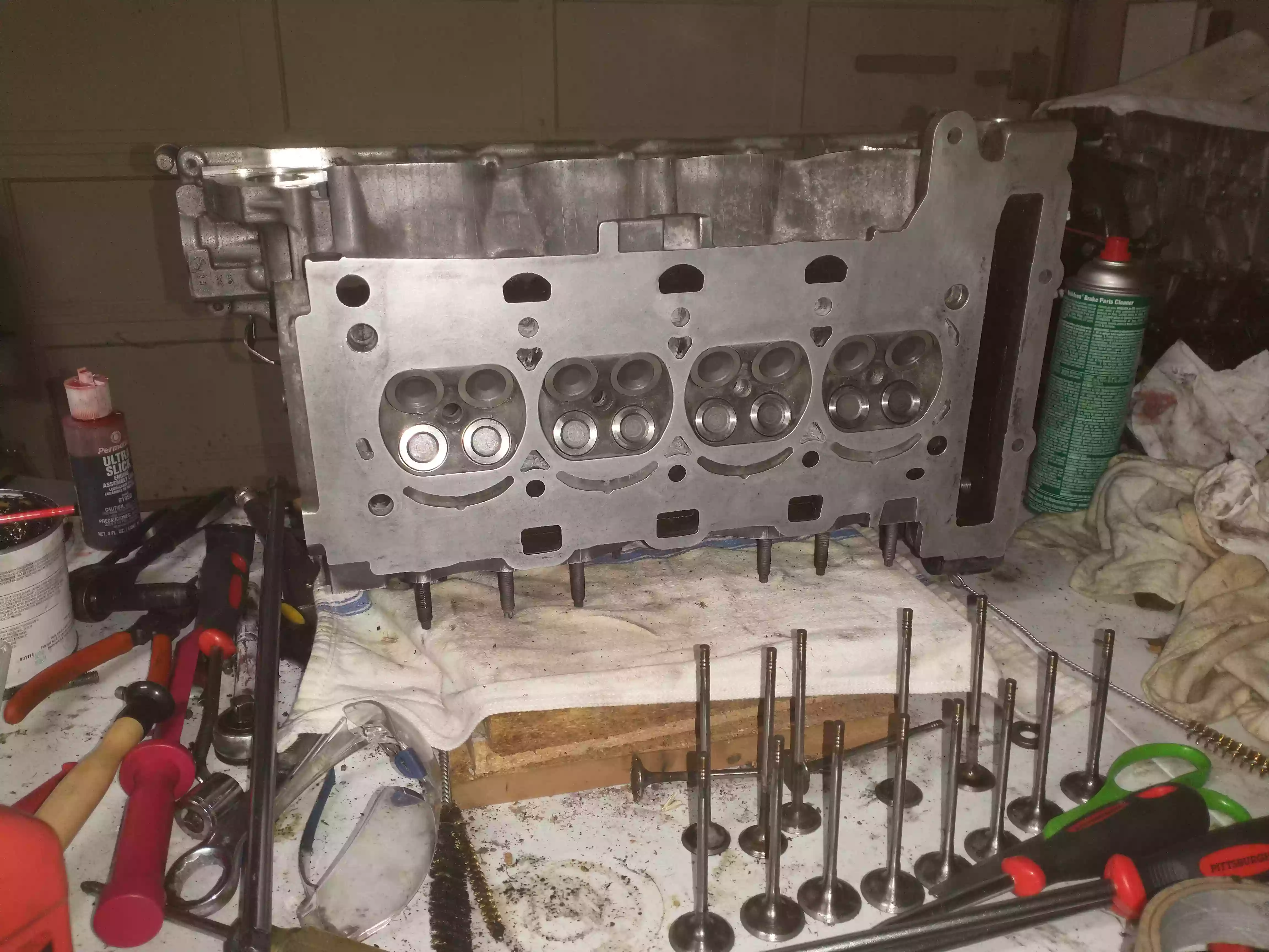
Below is the finished result of the valve-job with the new valves installed into the head via their springs, keepers, and seals as well as the cleaned surface of the engine head. Pictured before the head are the old valves.
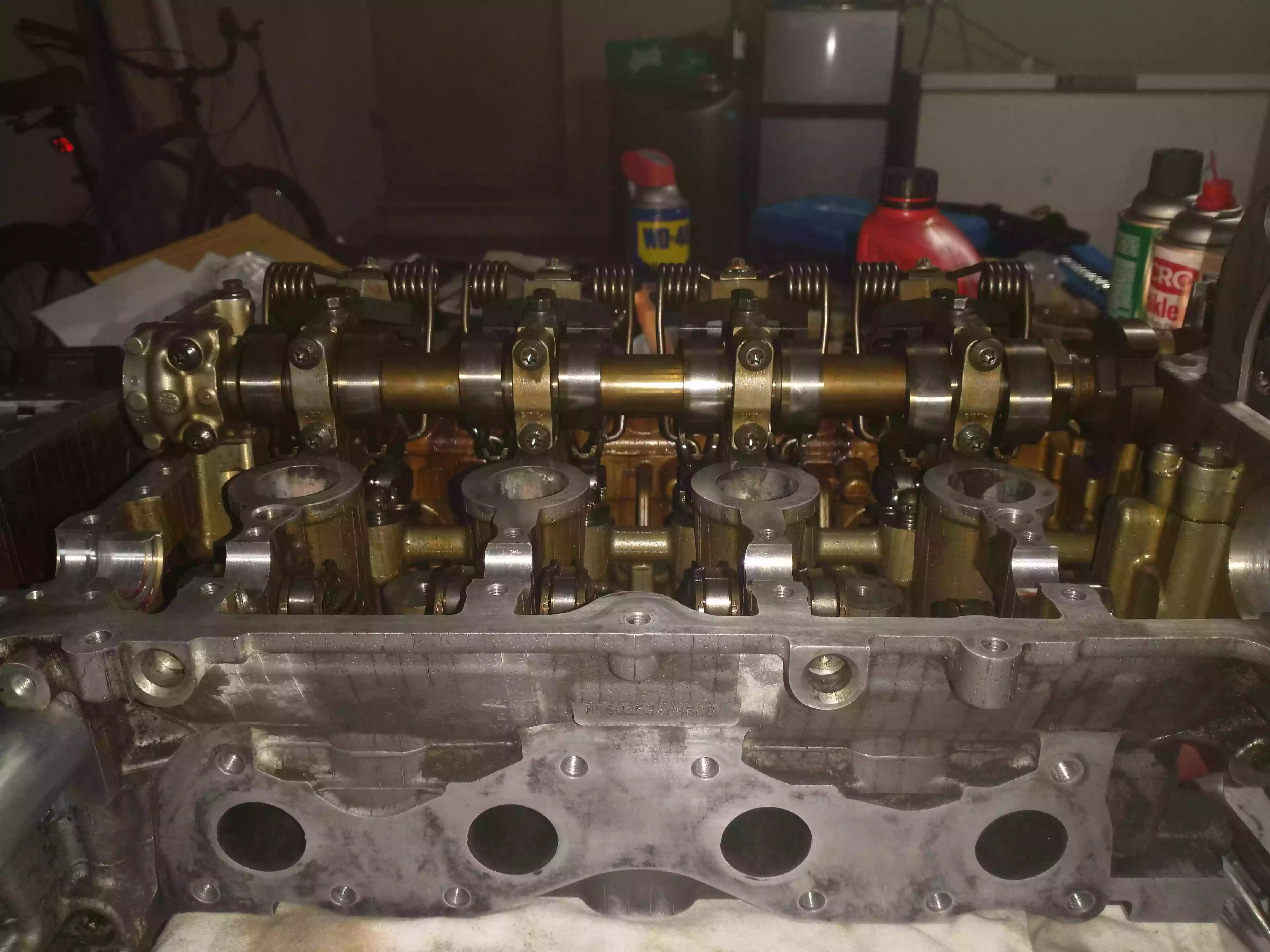
Here is an image of the reassembled Valvetronic system and intake camshaft. As you can see, the eccentric shaft sits in journals within the head itself, while the intake camshaft sits higher up in the head within journals comprised of external components. BMW suggests that a highly expensive special tool be used to appropriately position the springs of the intermediate arm. Heeding this suggestion is well advised, as the strength of these springs is dangerous. However, I opted to use a notched pin-prying tool to push the springs behind the intake camshaft and into their respective roller notches. This method was time consuming and risky compared to that which is suggested in the repair manual, but I was able to successfully reassemble the Valvetronic system without hurting myself.
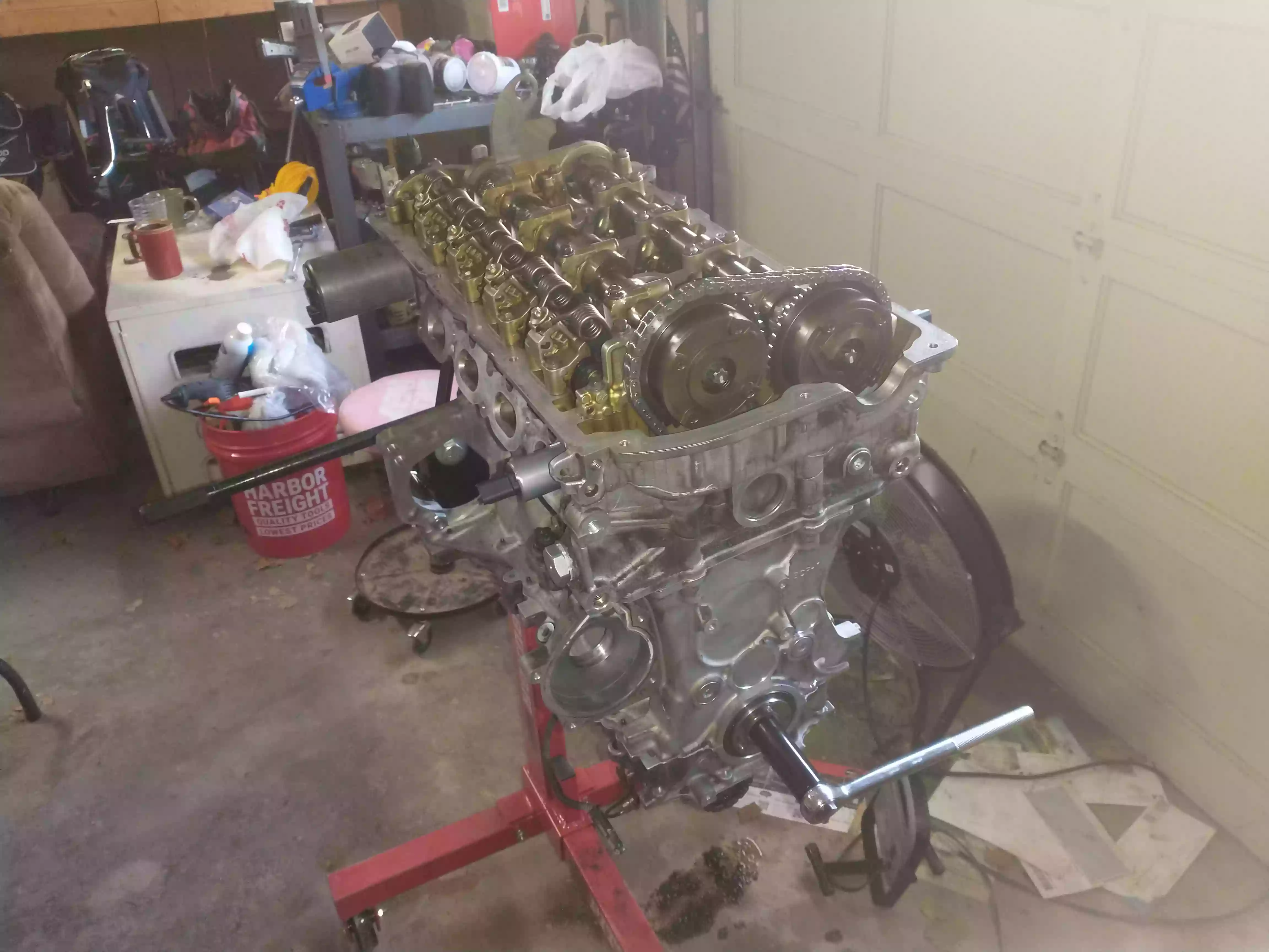
This is the final image of the engine before it was moved back to the hoist which was used to extract it from the vehicle. As you can see, the exhaust camshaft is present along with the VANOS gears and timing chain. All that is missing from the core of the engine in this image are the valve cover and sump.
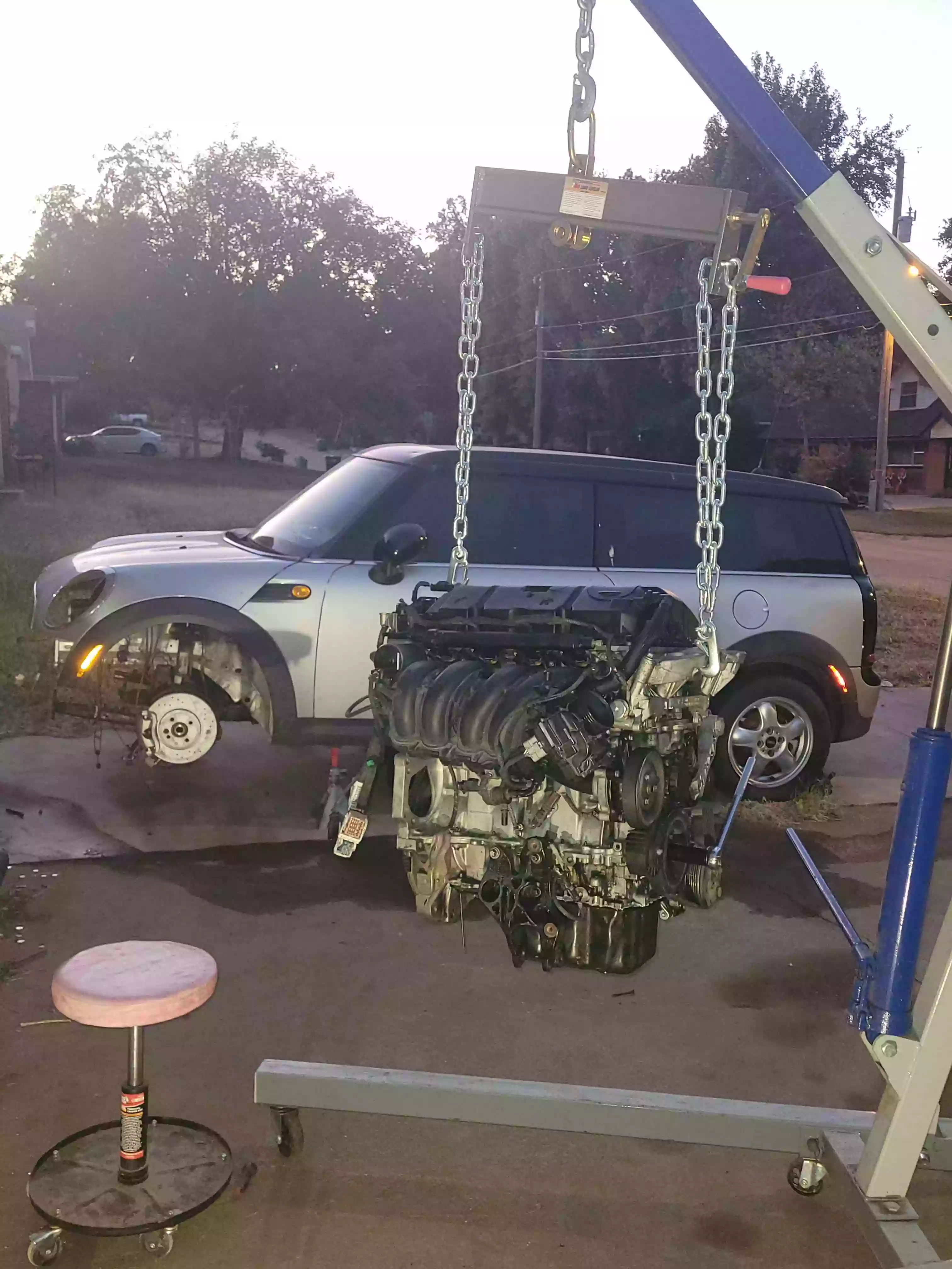
Prior to lifting the engine back onto the hoist I reinstalled the intake manifold, water pump, alternator, compressor, idler pulley, thermostat, oil filter housing, vacuum pump, and the primary wiring harness. This is my favorite picture taken throughout the project, and showcases the rebuilt engine centered in front of the car.
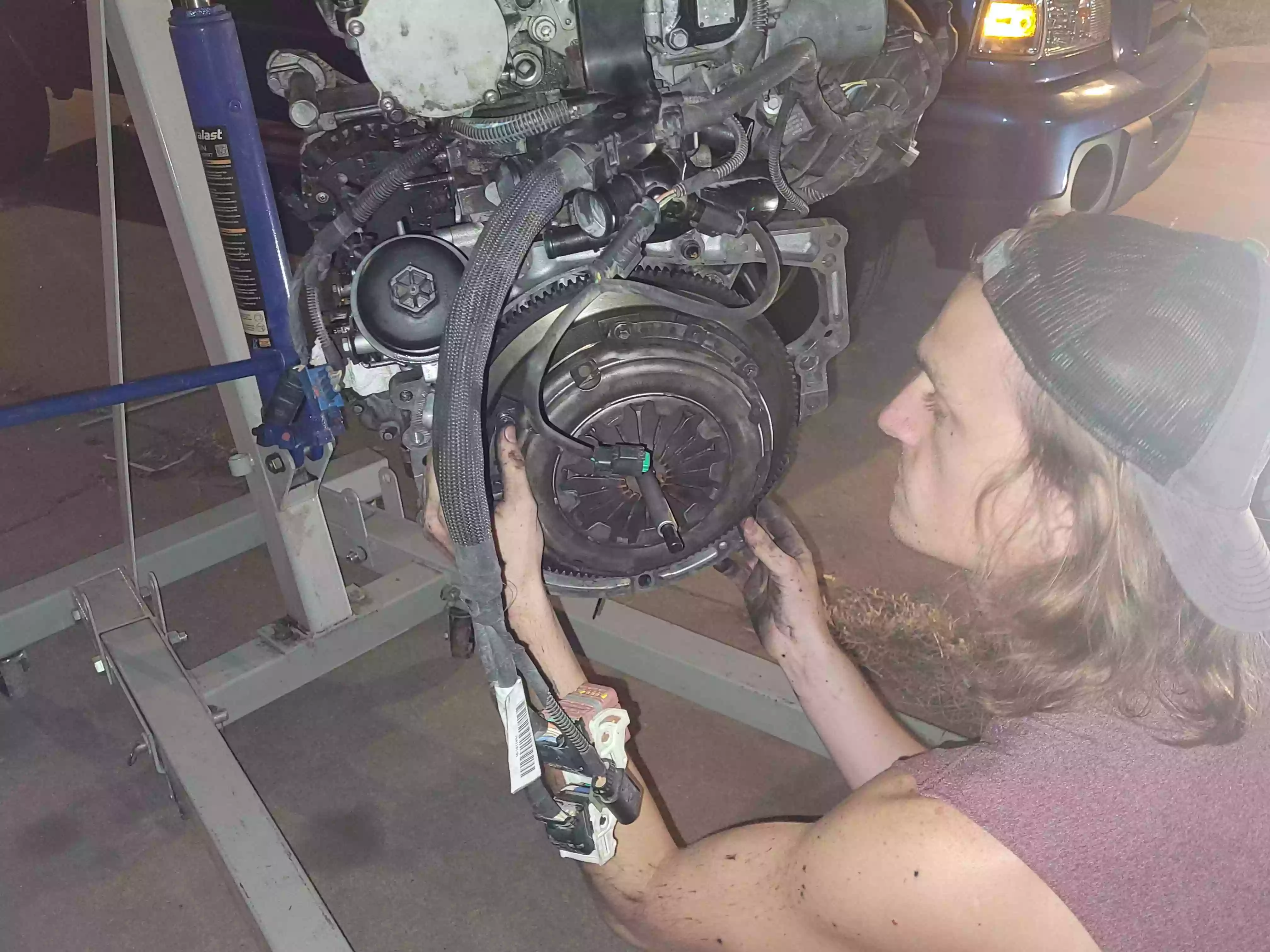
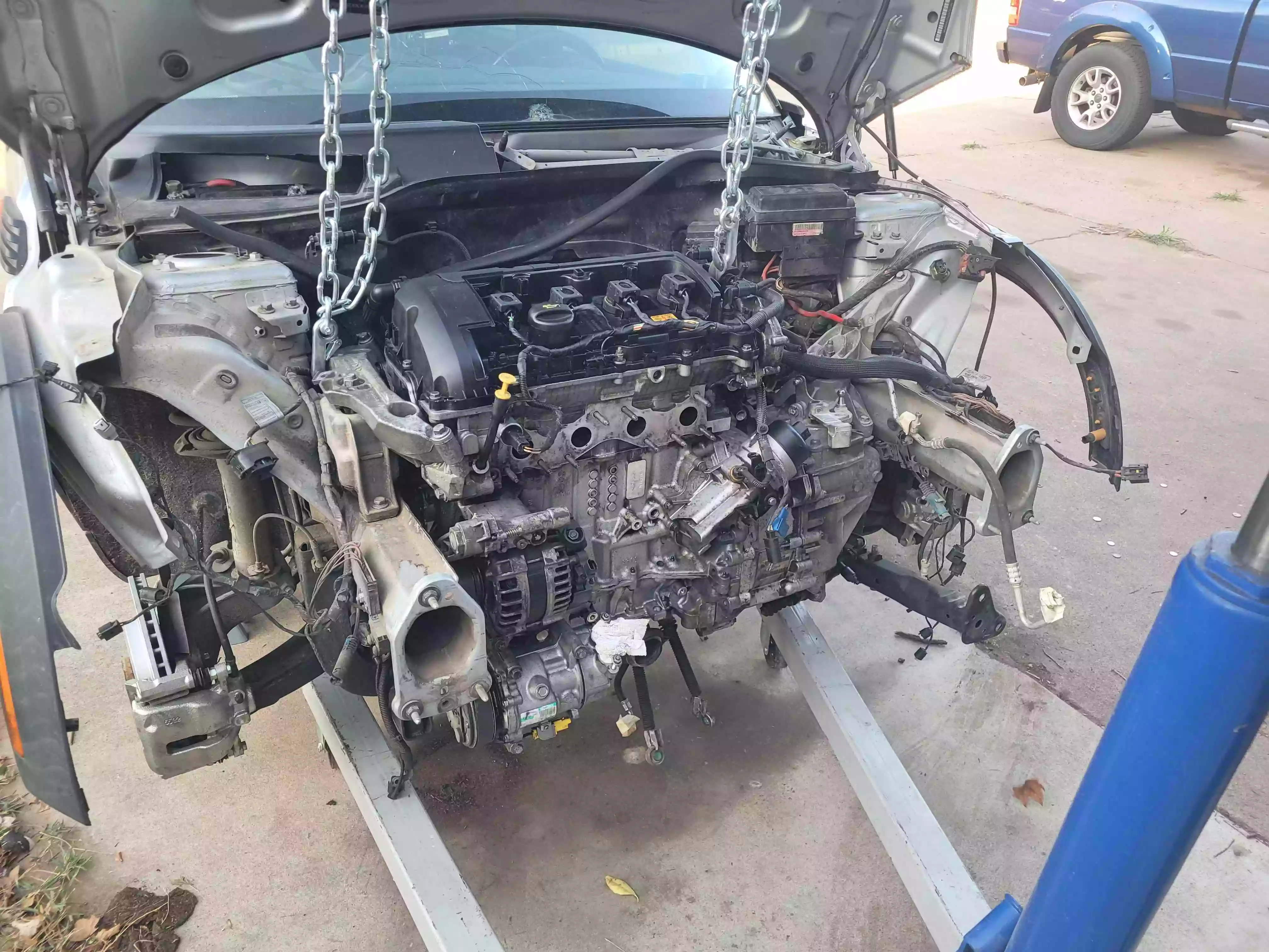
The engine bay of the Mini Cooper is as small as you might imagine, so I removed the engine with the transmission as the repair manual suggests. This proved to be less of an inconvenience than I expected, as the transmission is only around 40 pounds and can be easily carried by hand. In any case, I reused the clutch and pressure plate as they showed little signs of wear.
I used a transmission jack to make the process of mating the transmission to the engine easier, after which I reinstalled the starter motor and prepared the car to receive its powerplant.
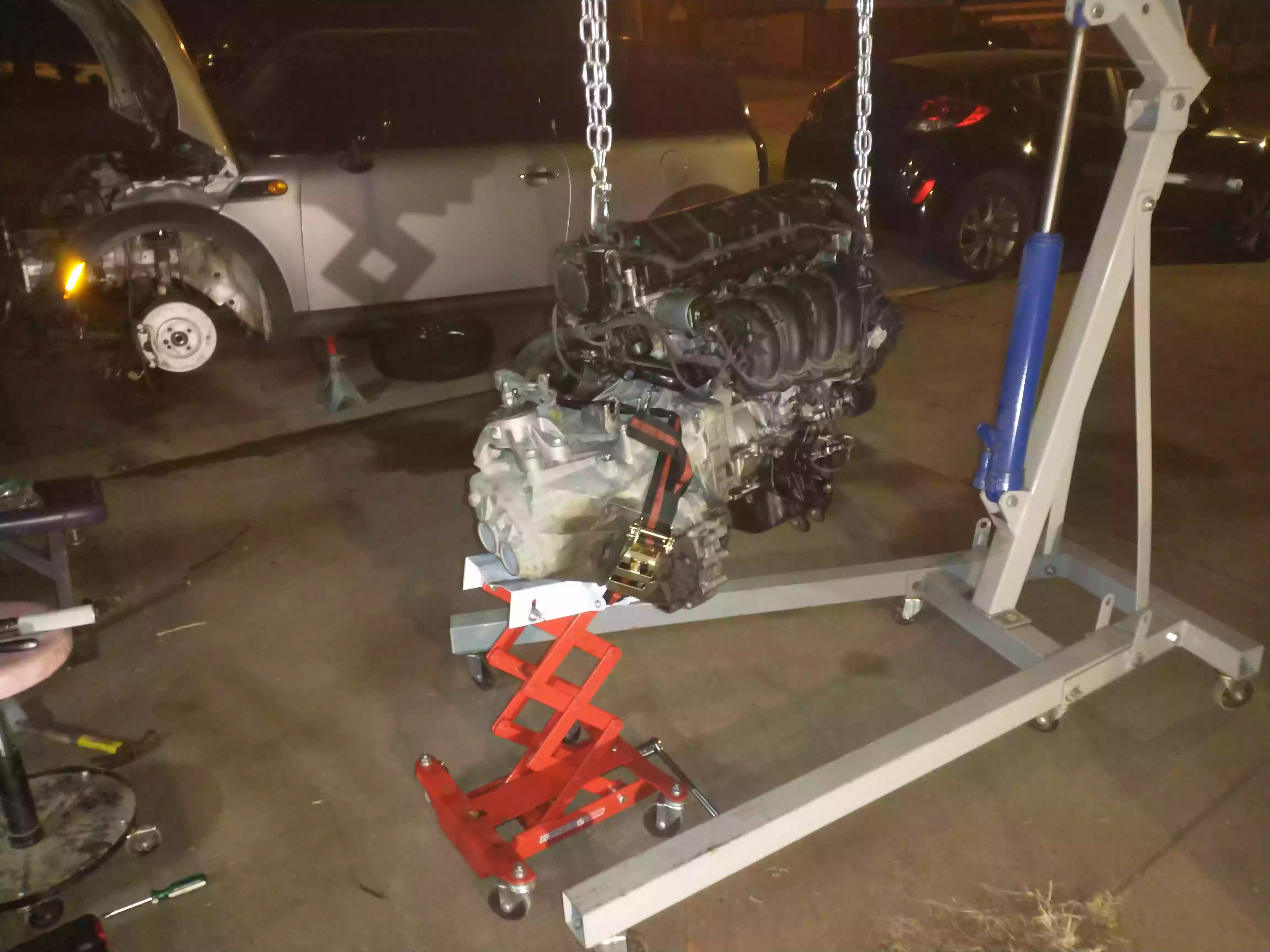
Moving the dangling weight of the powerplant and positioning it on the mounts within the vehicle was difficult, but was done successfully without damage to the engine or its surroundings. At this point in the project I received help from my brother and a few friends to put the engine in a position to run temporarily. We installed the exhaust manifold, intake filter, throttle body, fuel system, clutch cylinder, and temporarily filled the cooling system with water.
First Run
Here is a video recording of the first time the engine was started after the rebuild. I could have primed the oiling system separately, but I wanted everyone who was generous enough to help me to see the engine run in person and time was short. In any case, the fuel filter was filthy and the fuel pump relay was working intermittently during this startup. This is the reason for the occasional hiccups during the brief first run. Despite these issues, the engine started and ran successfully, and full fuel pressure was achieved roughly 29 seconds into the video at which point an audible change occurs.
Overbore and Oversized Pistons
The engine started to show signs of excessive crankcase pressure and oil consumption following the rebuild. These symptoms are expected to a degree following a rebuild as new piston rings need time to set, but they never abated. Rather, the crankcase pressure was becoming so severe as to steadily eject oil from the front main seal. This of course made me suspect that the engine was suffering from piston blow-by, as the PCV valve seemed to be functioning properly. Thus, I removed the head again, along with each piston. The new pistons measured at the same size to a thousand of an inch. However, every cylinder within the block was either close to, or beyond the 0.1mm tolerance for piston to wall clearance. Moreover, a few of the cylinders were at the conicity limit, but this would likely be ameliorated by the clamping force of the head to the block once the engine is assembled. In any case, I’ve decided to have the cylinders overbored and fit the engine with oversized (+0.5mm) pistons.
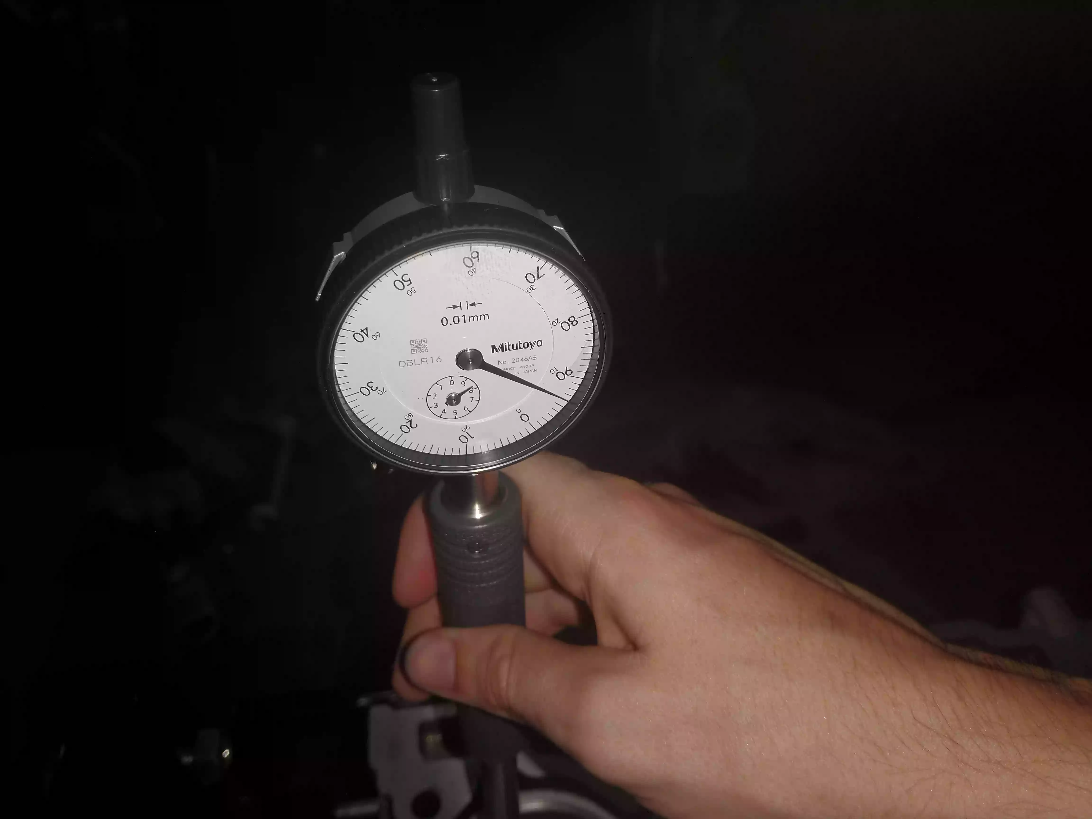
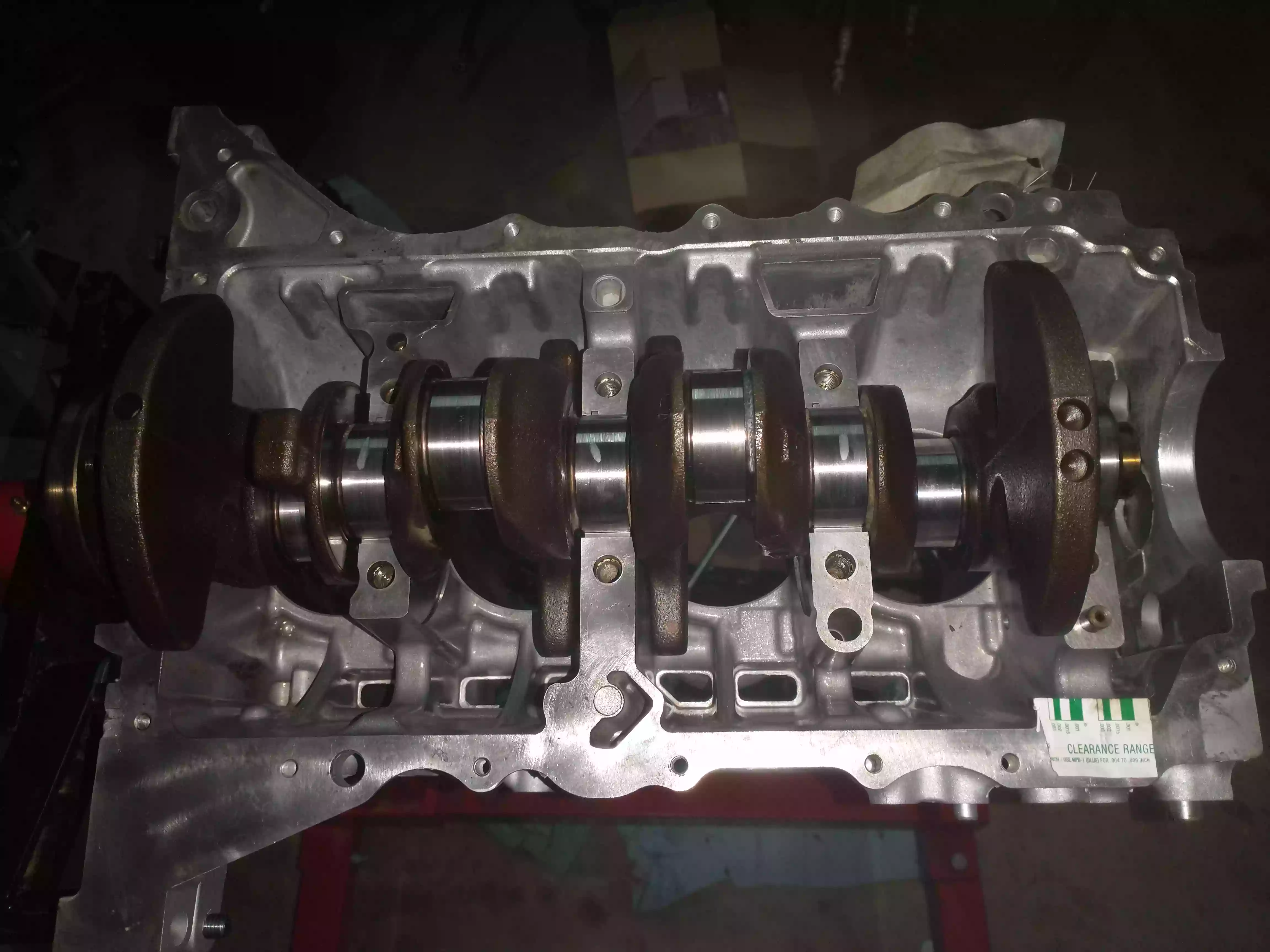
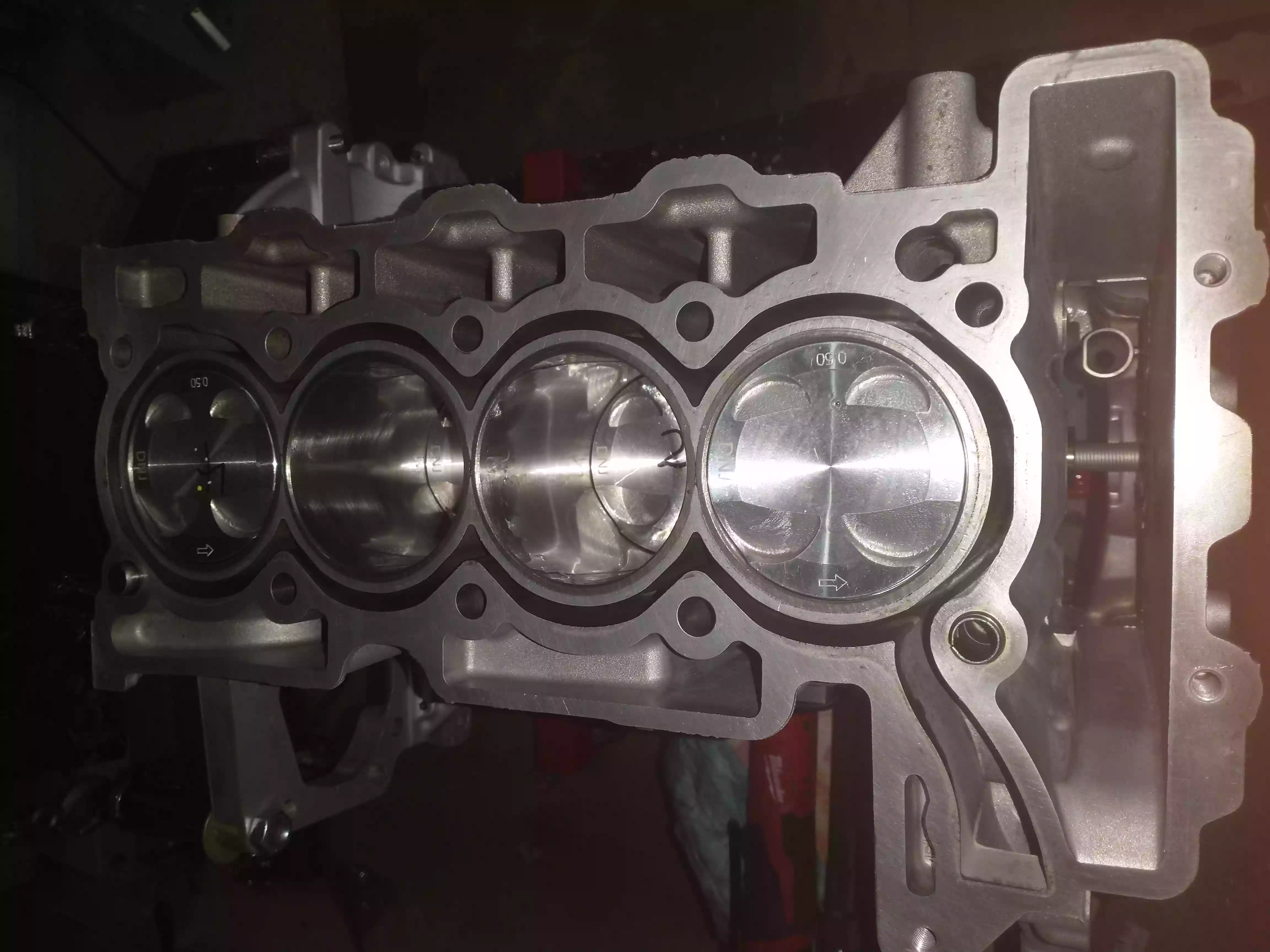
The shop did an excellent job with the overbore, as each cylinder measured to 0.06mm clearance after the bore and hone. I won’t describe the entire rebuild process again, but pictured below is the shortblock with the new pistons and rings installed.
This time around I decided to verify the bearing clearances on both the mains and connecting rods with plastiguage. I now have access to a dial bore gauge, but the connecting rod bearings are new and the main bearings are original to the engine. Thus, it was more expedient to use platigauge. All of the bearing clearances measured within tolerance as expected.
