In the Spring of 2022 I went back to school to pursue a master's degree in electrical engineering, about six months after my last correspondence with Oklahoma State's TurboElectric Research Team.
During that time period the team was supplied with funding to construct and document the creation of a high power turboelectric test bench for the FAA.
The team made tremendous progress towards the assembly, installation, and reformation of the engine and frame by the time I became reinvolved, but most of the electrical work was either unfinished or in need of refinement.
Thus my tasks for this project were to handle the integration of the aircraft's electrical systems. All three of us who were involved on this project are named Josh: Josh Drake, Johnsen, and Melvin.
Melvin is an aircraft mechanic with a Master's degree in aerospace engineering. He handled the design and assembly of everything mechanical on the system.
Johnsen is a PhD candidate in aerospace engineering. He had the most general role on the project, and was involved to at least a cursory degree in almost every aspect of it.
He wrote the data acquisition code and the reports for the project in addition to all of his more direct contributions.
System Overview
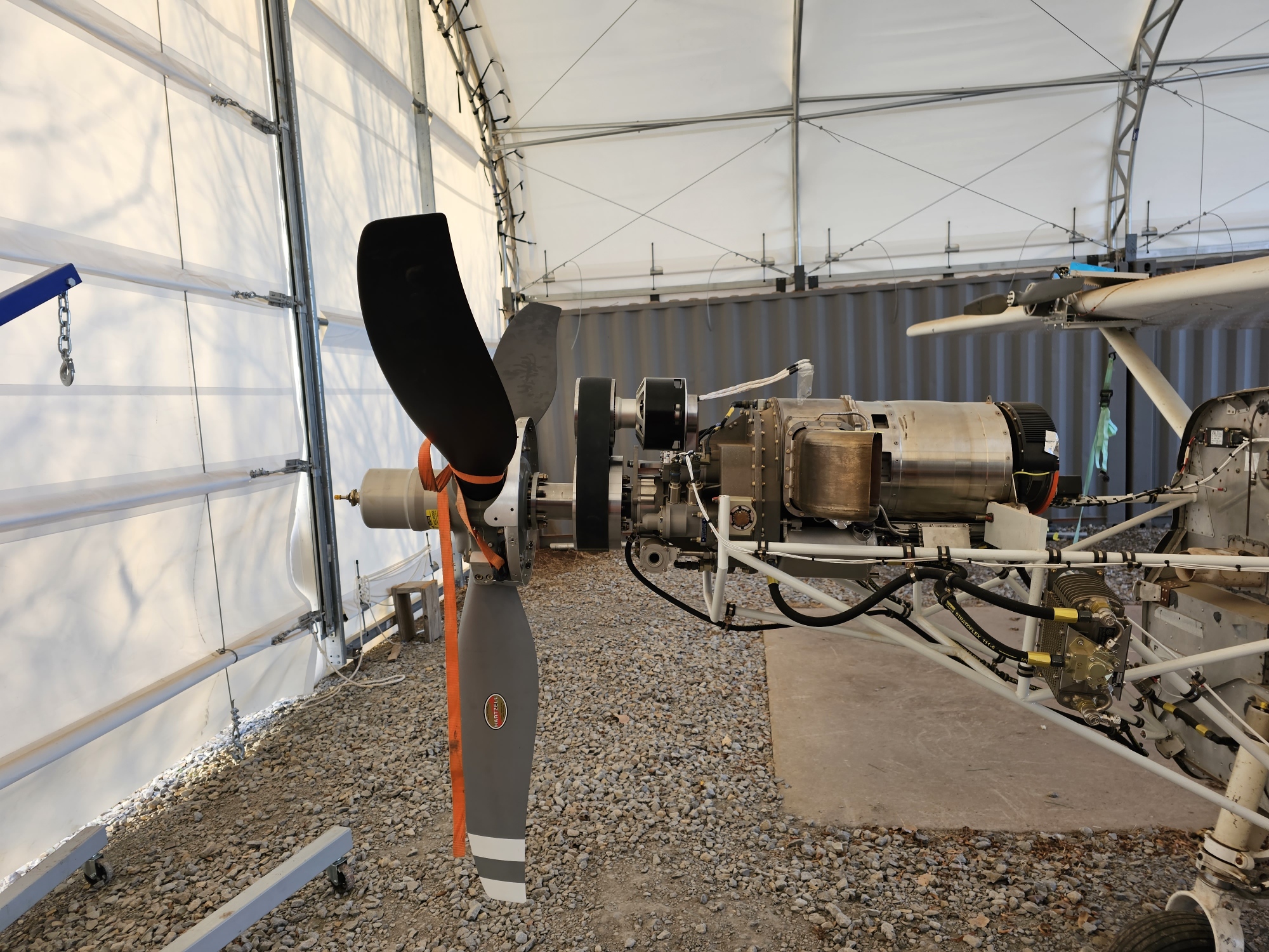
The first component that was designed and added to the system after my arrival was the custom pully and mount pictured below.
Melvin's pully apparatus couples the system's generator to the turbine engine, and provides a small reduction to boot.
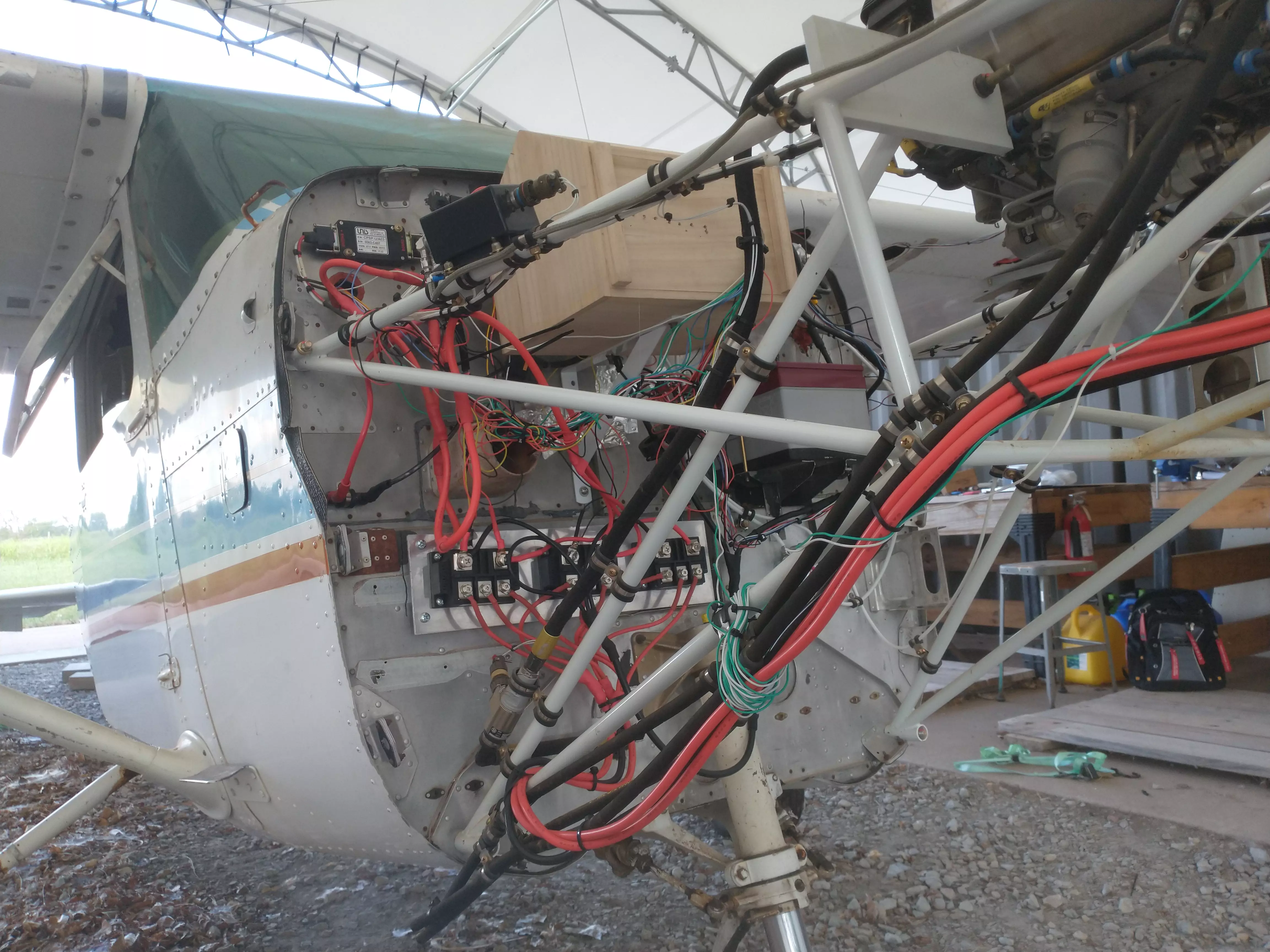
Below is an image of the system's electrical wiring. Three full bridge rectifier modules are wired in parallel atop a heatsink towards the bottom of the fuselage firewall,
above and to the left of which is the high voltage system's precharge contactor and resistor. Despite their being obstructed by the birdhouse housing the circuit boards in the particular image below,
the crowbar circuit resistor and relay are above the avionics battery seen on the right. This circuit discharges superfluous power through a large resistor if the high voltage bus exceeds its voltage threshold.
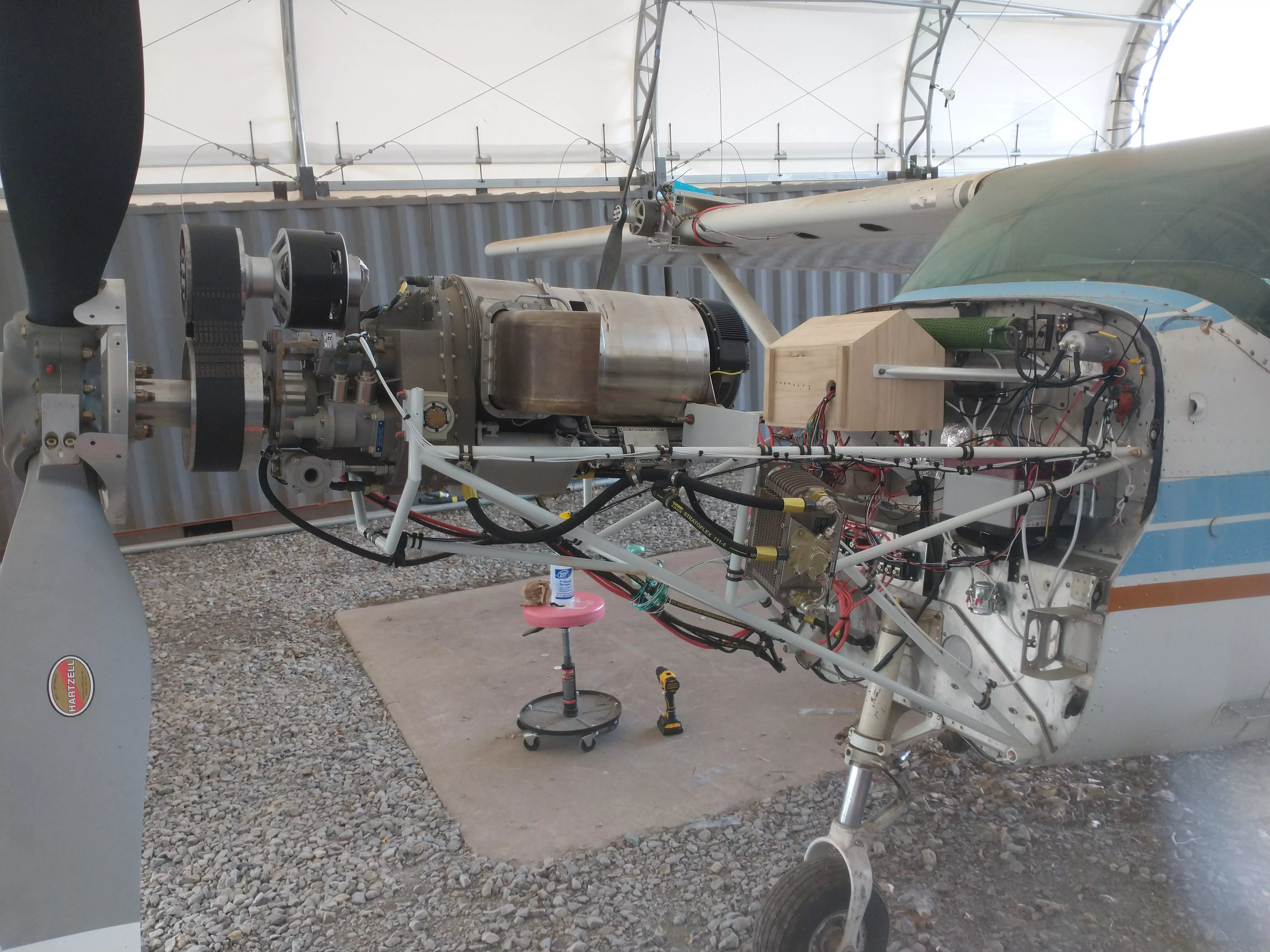
Lastly is an image containing the completed system in its entirety. The aforementioned crowbar circuit and its accompanying components are visible behind the electronics birdhouse.
The electronics birdhouse contains an analog circuit to actuate the high voltage bus' contactor once the system is precharged,
a simple circuit for actuating the crowbar contactor comprised of little more than a few zener diodes and a photocoupler, and a few microcontrollers outfitted with custom shields that I designed for
data acquisition. Greater attention is provided to these boards below.
Circuit Boards
I had originally intended for this section to detail the boards I designed and fabricated for the project along with schematic and layout pictures,
but I yet again neglected to create backups for my KiCAD projects and no longer have access to my schematics or layouts.
Fortunately, I don't intend on repeating this mistake for a third time and now have a dedicated section on my Git server for PCB projects.
However, I will describe the functionality of these boards and provide you with pictures of their completed forms.
Precharge Board
This board connects the system's high voltage battery to its capacitive components through either a small relay and precharge resistor, or through a large contactor.
The state transitions from connection through the precharge resistor to main contactor once the high voltage bus is within five volts of the battery.
This process takes around one second, after which the precharge resistor is disconnected, the main contactor closes, and the system can proceed with normal operation.
In the absence of this board the high voltage batteries would be damaged, mostly likely severely, by the massive inrush current demanded by the bus' large capacitance.
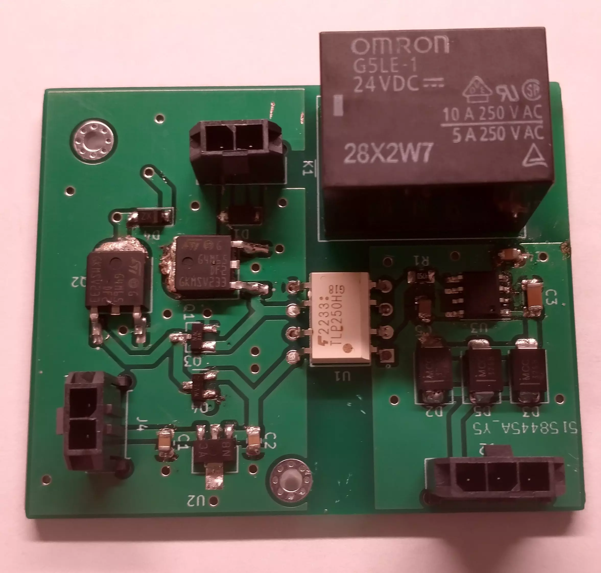
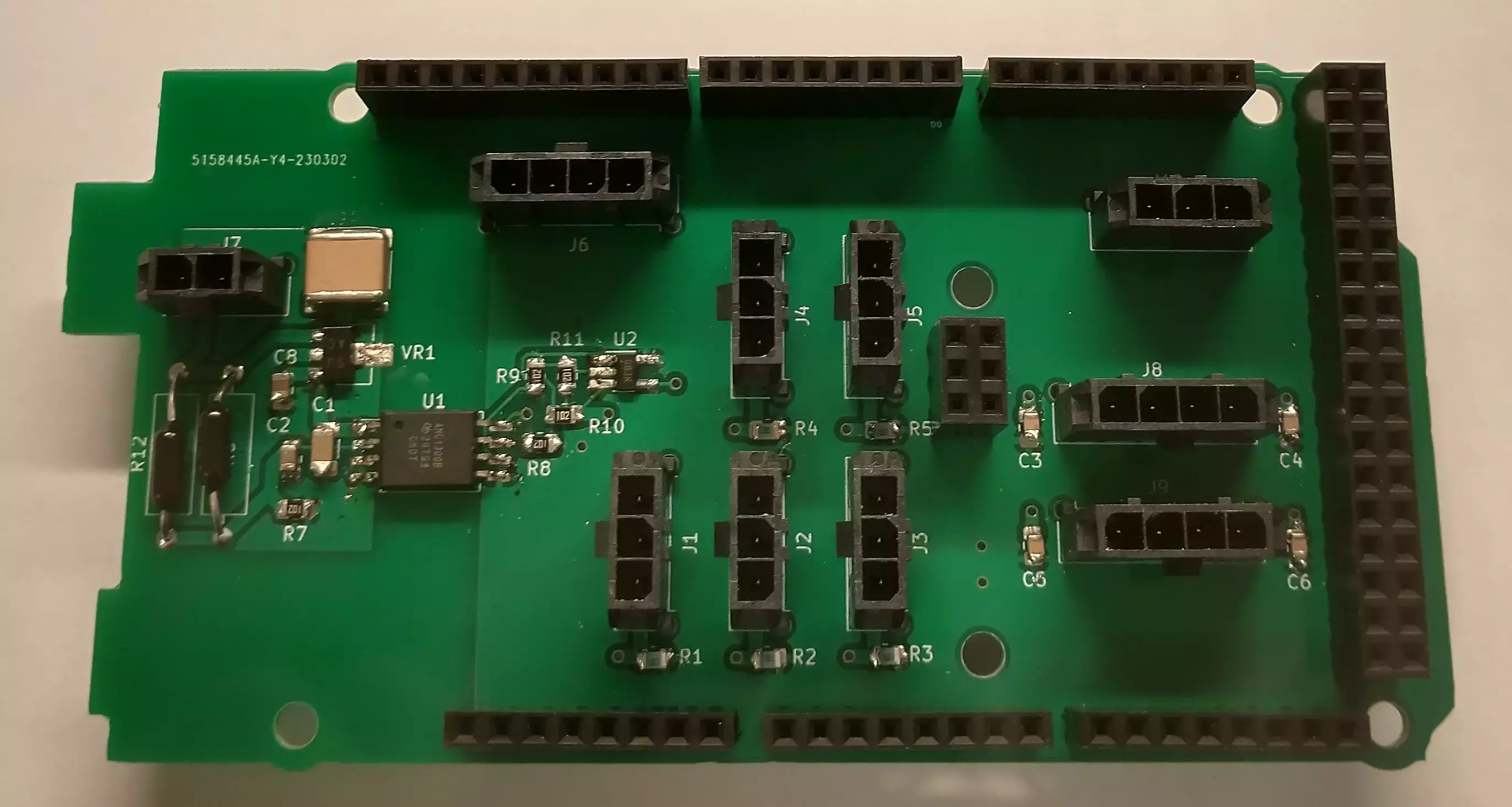
Arduino Shields
I made two copies of the board pictured below for the system. It features an isolated voltage measurement circuit,
attachment connectors for various thermal couples and current sensors, and a connector for a pressure sensor over I2C.
These shields slot into Arduino Megas which were used to record performance data from the tests we ran on the system.
Crowbar Control Board
I'll refrain from including a picture of this board as it's simple and small, but it serves an important purpose in protecting the battery and system as a whole.
In the event that the system voltage were to exceed the maximum battery voltage by 10 volts, a photocoupler would be actuated, causing an IGBT to turn on to allow for the coil of the crowbar contactor to become energized.
This shorts the high voltage bus to ground through a large ceramic resistor, allowing for this excess power to dissipate without harming the system.
Full System Test
Here is a recording of the final run of the system. You may notice that the left propeller isn't spinning.
This is a consequence of the fact that its inverter was already broken, or at least its ability to determine position was compromised.
We ran the left propeller by itself after the test when it subsequently burst into flames and smoldered for ten minutes.
Fortunately, the test was an overall success in spite of this failure, as the electric motors used to drive the propellers and the system's generator are identical.
This allowed us to achieve a maximal electric load with the right propeller by itself.